Configuration
CNT-SVX05B-EN 79
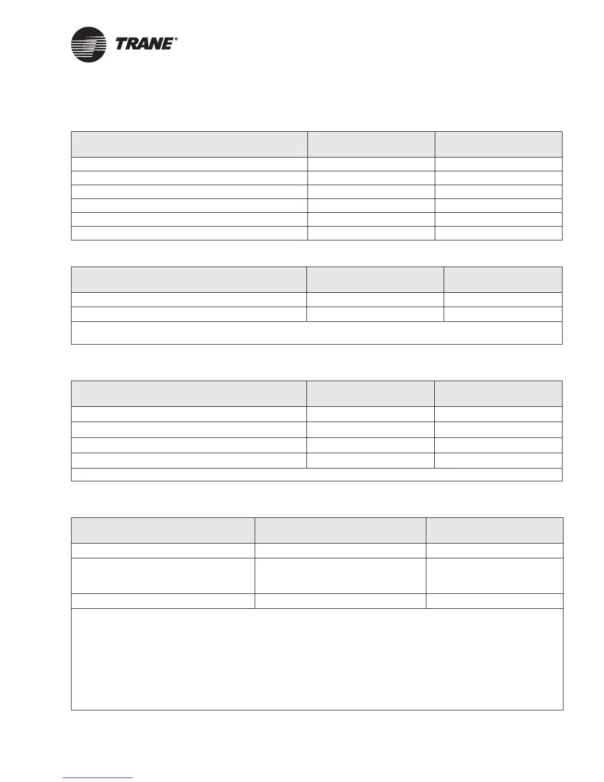
Table 44. Discharge air temperature control setpoint configuration
Setpoints and limits Valid range Default value
Discharge air temperature cooling setpoint 32°F to 86°F (0°C to 30°C) 55°F (12.8°C)
Discharge air temperature heating setpoint 50°F to 158°F (10°C to 70°C) 100°F (37.8°C)
Discharge air temperature cooling setpoint high limit 32°F to 86°F (0°C to 30°C) 68°F (20°C)
Discharge air temperature cooling setpoint low limit 32°F to 86°F (0°C to 30°C) 44.6°F (7°C)
Discharge air temperature heating setpoint high limit 32°F to 158°F (0°C to 70°C) 104°F (40°C)
Discharge air temperature heating setpoint low limit 32°F to 158°F (0°C to 70°C) 86°F (30°C)
Table 45. Daytime warm-up setpoint configuration
Parameter Valid range Default value
Daytime warm-up start setpoint
1
40 to 87.0°F (4.4 to 30.6°C) 62°F (16.7°C)
Daytime warm-up termination setpoint
2
43 to 90°F (6.1 to 32.2°C) 71°F (21.7°C)
1
When the space temperature is below the daytime warm-up start setpoint, the daytime warm-up sequence is initiated.
2 When the space temperature is above the daytime warm-up stop setpoint, the daytime warm-up sequence is terminated.
Table 46. Duct static pressure setpoint and limit configuration
Parameter Valid range Default value
Duct static pressure high limit
1
0 to 5 inH
2
O (0 to 1250 Pa) 4 inH
2
O (1000 Pa)
Duct static pressure setpoint 0 to 5 inH
2
O (0 to 1250 Pa) 1.5 inH
2
O (375 Pa)
Duct static pressure setpoint high limit 0 to 5 inH
2
O (0 to 1250 Pa) 3 in H
2
O (750 Pa)
Duct static pressure setpoint low limit 0 to 5 inH
2
O (0 to 1250 Pa) 0.5 inH
2
O (125 Pa)
1 This is the pressure at which the controller shuts down the unit to prevent duct damage.
Table 47. Mixed-air temperature control configuration
Parameter Valid range Default value
Mixed-air low limit setpoint
1
-4°F to 104°F (-20°C to 40°C) 48°F (8.9°C)
Mixed-air control sequence
2
• None
• Mixed-air control
• Mixed-air preheat control
Dependent on air-handler type
Pre-ventilation setpoint
3
32°F to 86°F (0°C to 30°C) 48°F (8.9°C)
1 If the mixed-air temperature reaches this low limit setpoint, the controller uses the configured mixed-air control sequence to
maintain mixed-air temperature above the configured mixed-air low limit setpoint.
2 The Tracer
AH540/541 controller can be configured three different ways to control mixed-air temperature above the mixed-air
low-limit temperature. If none is selected, the controller does not attempt to prevent low mixed-air temperature conditions. Low
temperature detect provides unit freeze protection from freezestat binary input IN7. Mixed-air control reduces the outdoor air
damper minimum position to maintain mixed-air temperature. The mixed-air preheat control sequence first attempts to use
preheat (if available) to maintain mixed-air temperature above the low limit temperature. If preheat capacity cannot maintain
the air-handling unit's mixed-air temperature above the configured mixed-air low limit temperature, the controller lowers the
outdoor air damper below its minimum ventilation position.
3 If discharge air temperature or mixed-air temperature is less than the pre-ventilation setpoint, heating capacity is energized
early in the unit start-up process.
 Loading...


