CNT-SVX09E-EN 11
Applications for the MP503
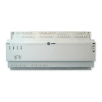
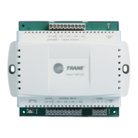
The MP503 is a field-installed device that is used to monitor inputs and control binary outputs. The
module has four (4) configurable inputs and four (4) binary outputs. This section provides
information about the function of inputs and outputs and examples of wiring applications for
MP503.
Inputs
The MP503 has four (4) inputs. Each input can be configured (in any combination) as:
•Binary
•Thermistor
•0–20 mA
• 0–10 Vdc.
The factory-default input type is a thermistor. To change the configuration of the input, use the
d
evice plug-in an
d a service tool, such as the Rover service tool. No jumpers need to be set on the
circuit board.
Binary Inputs
When an input is configured as binary, the MP503 equates a signal of 0 Vac with open contacts and
24 Vac with closed contacts.
Thermistor Inputs
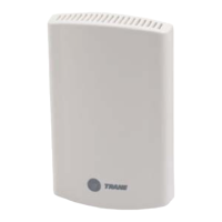
Thermistor inputs are used to measure temperature. They must be Trane 10kW (at 25°C)
thermistors. Any Trane zone temperature sensor can be connected to the MP503; however, the
module will not recognize the setpoint thumbwheel or fan speed switch that appears on some
sensors.
0–20 mA Inputs
Many common sensors, such as humidity, pressure, and flow sensors, provide a 4–20 mA output.
Any of these types of sensors can be connected to an input on the MP503 and configured for 0–
20 mA.
Important:
Because most sensors have 4–20 mA outputs rather than 0–20 mA outputs, some
scaling is required. The scaling cannot be done on the MP503. The MP503 transmits
the raw mA reading.
To power these sensors, 24 Vdc is available from the MP503 circuit board (refer to Figure 5, p. 12).
0–10 Vdc Inputs
The MP503 can read a value from a sensor that provides a 0–10 Vdc signal.
Important:
When using a sensor with a smaller range (such as 2–10 Vdc or 6–9 Vdc), some
scaling is required. The scaling cannot be done on the MP503. The MP503 transmits
the raw voltage reading.
To power these sensors, 24 Vdc is available from the MP503 circuit board (refer to Figure 5, p. 12).
 Loading...
