20 CNT-SVX09E-EN
Status Indicators
Status Indicators
This section provides information about the following:
• MP503 circuit board
• Service pin button
• Interpreting LEDs
• Diagnostics
MP503 Circuit Board
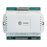
Figure 10 shows the location of the Service Pin button, the Neuron ID label, and LEDs.
Figure 10. Tracer MP503 I/O module circuit board
Service Pin Button
The Service Pin button is located as shown inFigure 10 above, and is used to:
• Identify a device
• Add a device to the active group
• Verify PCMCIA communications
• Make the Status (green) LED wink to
verify that
the module is communicating on the link
Refer to the Rover Opera
tion and Programming Guide (EMTX-SVX01).
LonTalk LED (yellow)
Neuron ID label
(on back of terminal block)
Service Pin button
Status LED (green)
Service LED (red)
Neuron chip
Binary output 1 LED (green) Binary output 2 LED (green) Binary output 3 LED (green) Binary output 4 LED (green)
 Loading...
