CNT-SVX09E-EN 9
General Wiring Information
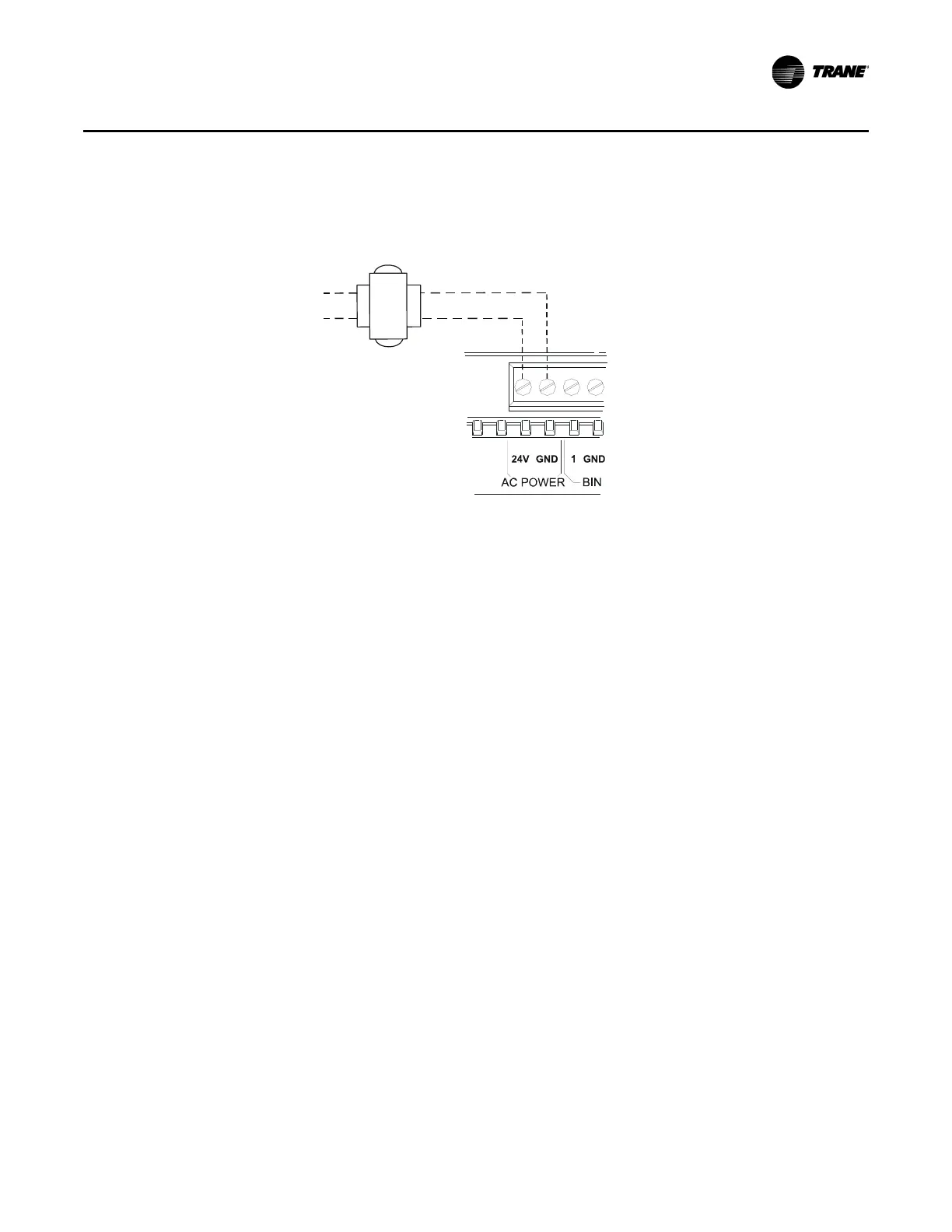
Figure 3. Connecting ac power wires to the module
H
N
24 Vac
transformer
Line
voltage
Use a UL-listed Class 2 power transformer supplying a nominal 24 Vac (20–30 Vac). The
transformer must be sized to provide adequate power to the MP503 (10 VA) and to the output
devices [including relays], to a maximum of 12 VA per output utilized. The MP503 may be powered
by an existing transformer integral to the controlled equipment, provided the transformer has
adequate power available and proper grounding is observed.
Communication Link Wiring and Addressing
The MP503 communicates with the BAS and with other devices through a LonTalk®
communication link.
Important:
For important instructions on network wiring, refer to the Tracer Summit™
Hardware and Software Installation Guide (BMTX-SVN01).
Wiring for the communication link must meet the following requirements:
• All wiring must comply with the Natio
nal Electric
al Code and local codes.
• 22 AWG Level 4 un-shielded communications wire recommended for most Comm5
installations
.
• Termination resistors are required for wiring LonTalk devices com
municating on a network. For
important instructions on using termination resistors for LonTalk applications, refer to the
Tracer Summit Hardware and Software Installation Guide (BMTX-SVN01).
Each MP503 has a unique 12-character alphanumeric device address for communicating on a BAS
network. This
address, referred to
as a Neuron ID, is assigned in the factory before the product is
shipped. Each device can be identified by viewing its unique Neuron ID, which is on a printed label
attached to the circuit board of the device. Additional adhesive-backed, peel-off Neuron ID labels
are tethered to the device for placing on mechanical prints or unit location worksheets. The Neuron
ID will appear when communication is established with a service tool (such as the Rover™ service
tool) or a BAS. An example Neuron ID is 00-01-64-1C-2B-00.

 Loading...


