22 CNT-SVX09E-EN
Status Indicators
Binary Output LEDs (4 Green)
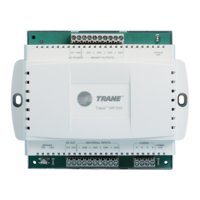
Four (4) green LEDs on the MP503 circuit board indicate the status of the four binary outputs (refer
to Table 10).
Diagnostics
Diagnostics do not affect the operation of the MP503. When the diagnostic clears, the module
resumes normal operation. All diagnostics generated by the MP503 are automatic (non-latching)
diagnostics. They clear automatically when the problem that generated the diagnostic is resolved.
Table 12 lists the diagnostics for the MP503.
Table 10. Binary output LEDs
Binary Output
(a)
(a) Each binary output LED reflects the status of the output relay on the circuit board. It may or may not reflect the status
of the equipment the binary output is controlling. Field wiring determines whether or not the state of the binary output
LED also applies to status of the end device.
LED Number
1 CR8
2 CR9
3 CR10
4 CR11
Table 11. Binary output LEDs
LED Activity Explanation
LED is on continuously. The relay output is energized.
LED is off continuously. The relay output is de-energized or there is
no power to the board.
Table 12. Diagnostics
Diagnostic Probable Cause Consequence Diagnostic Type
Normal The MP503 has just been pow-
ered or a clear alarm com-
mand has just been sent to the
MP503.
None—this is expected
behavior.
N/A
24 Vdc failure The 24 Vdc circuit is no longer
providing the correct supply
voltage.
All binary outputs go off. Automatic (non-latching)
Input configuration
changed
The configuration of one of the
inputs has been changed.
None—this is only informa-
tion.
Automatic (non-latching)

 Loading...


