Chapter 4 Applications for the heat pump configuration
24 CNT-SVX06B-EN
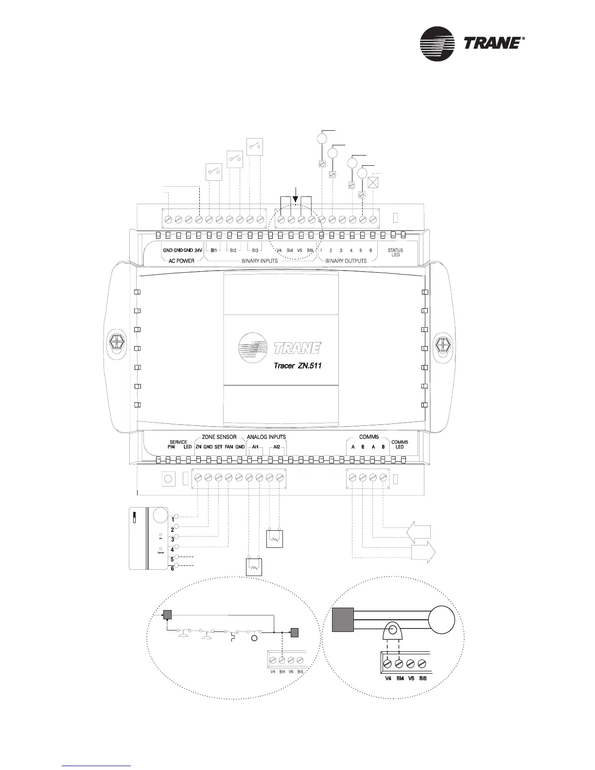
Figure 8. Wiring diagram for heat pump applications, with all required
and optional components connected
LonTalk
in
out
Leaving water
temperature
Discharge air
temperature
Reversing valve
Compressor 1 contactor
Compressor 2 contactor
Fan
Condensate overflow (open=normal)
Occupancy/Generic (open=occupied)
LonTalk
24 Vac (R)
Neutral (C)
GND*
Damper actuator/Generic
See
Details A & B
Detail A
Compressor-contactor
monitoring
Detail B
Compressor line-voltage
monitoring
Low-temperature detection (open=normal)
*The grounding wire of
binary output 6 should be
connected to one of the AC
POWER (GND) terminals.
G
Y1
Y2
B/O
OR