Service button (pin)
CNT-SVX06B-EN 59
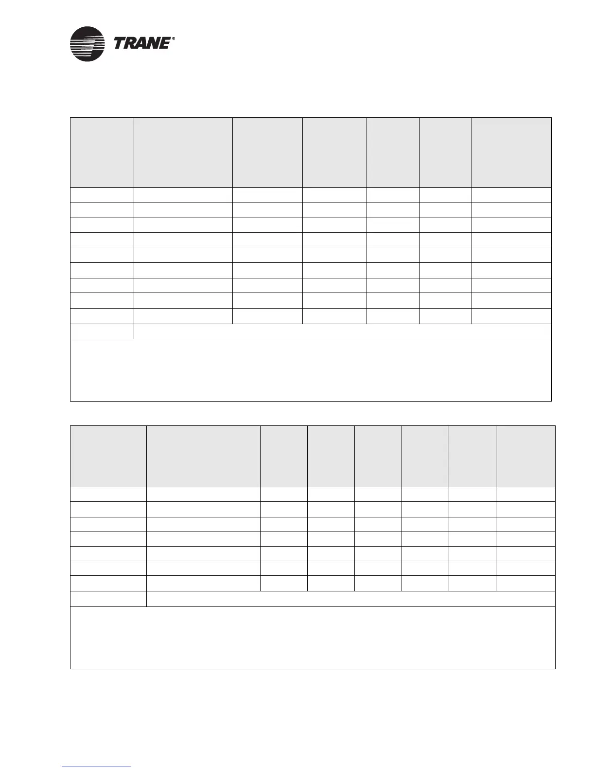
Table 13. Manual output test sequence for water-source heat pump configurations
Step
(number of
times Test
button is
pressed in
sequence)
Result Fan (BOP1)
Reversing
valve (BOP2)
Comp. 1
(BOP4)
Comp. 2
(BOP5)
Damper/
Generic (BOP6)
1 Begins test mode Off Off Off Off Closed/Off
2
Fan on
1
On Off Off Off Closed/Off
3 Reversing valve on On On Off Off Closed/Off
4Compressor 1 On On On Off Closed/Off
5
Compressor 2
2
On On On On Closed/Off
6
Compressor(s) off
3
On Off Off Off Closed/Off
7Heat 1 On Off On Off Closed/Off
8
Heat 2
2
On Off On On Closed/Off
9
Outdoor air damper
4
On Off Off Off Open/On
10
Exit
5
1
At the beginning of Step 2, the controller attempts to clear all diagnostics.
2
BOP5 will be controlled during this step regardless of its configuration.
3
This stage helps avoid an abrupt transition from cooling to heating by turning off the compressors prior to changing the
reversing valve state.
4
BOP6 will be controlled during this step regardless of its configuration.
5
This step will exit the manual output test and initiate a reset to restore the controller to normal operation.
Table 14. Manual output test sequence for 1 heat/1 cool configurations
Step (number
of times Test
button is
pressed in
sequence)
Result
Fan high
(BOP1)
Fan
medium
(BOP2)
Fan low
(BOP3)
Cool
output
(BOP4)
1
Heat
output
(BOP5)
1
Damper/
Generic
(BOP6)
1 Begins test mode Off Off Off Off Off Closed/Off
2
Fan high
2
On Off Off Off Off Closed/Off
3Fan medium OffOn Off Off Off Closed/Off
4 Fan low Off Off On Off Off Closed/Off
5Cool On Off Off On Off Closed/Off
6Heat On Off Off Off On Closed/Off
7
Outdoor air damper
3
On Off Off Off Off Open/On
8
Exit
4
1
For all 1 heat/1 cool applications including 2-pipe changeover, BOP4 energizes in the cool test stage and BOP5 energizes in the
heat test state, even though during normal unit operation BOP4 may control the unit valve for both cooling and heating (2-pipe
changeover).
2
At the beginning of Step 2, the controller attempts to clear all diagnostics.
3
BOP6 will be controlled during this step regardless of its configuration.
4
This step will exit the manual output test and initiate a reset to restore the controller to normal operation.