Installation - Mechanical
CLCH-SVX009A-EN 25
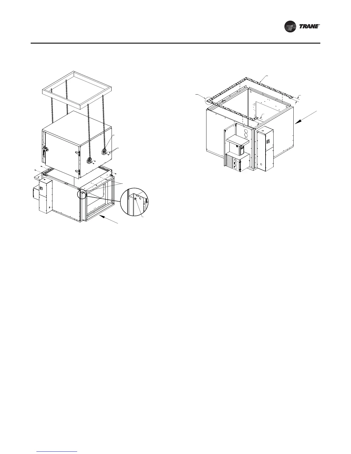
Repeat steps 1-6 in reverse order to reinstall second level
fan portion on the first level portion of unit. Lifting lugs
should be removed once reassembly is complete. Check
gasket between the two sections. In the event the gasket
between the two sections is damaged, replace with new
gasket (Item 4) (Part# GKT03823). See Figure 19.
Note: If unit is equipped with a control interface, VFD or
electric heat, disconnect electrical wiring. Wiring
between fan motor and contactor or VFD can be
disconnected via quick connects in the control
interface or VFD box respectively. Electric heat
wiring should be disconnected from switch in
control interface box. Any controls low voltage end
devices located in second level fan portion should
be disconnected via quick connects at each device.
Figure 18. Use spreader bars to lift top unit
(3) Screw:
0.250 - 14 x 0.750 self driller
(3) Screw:
self-driller
Detail A
(2) Screw:
0.313 - 18 x 0.875 sheet metal
Airflow
(1) Lifting lug #LUG00180
Temporarily use for lifting second level.
Figure 19. Check gasket between sections, replace if
necessary
4.25
2.25
First Level
Airflow
Joint gasket
should overlap
1/2 inch
(4) Gasket: 0.188T x 1.50W
# GKT03823
Align to the edge of the panel.