14 CLCH-SVX009A-EN
Dimensions and Weights
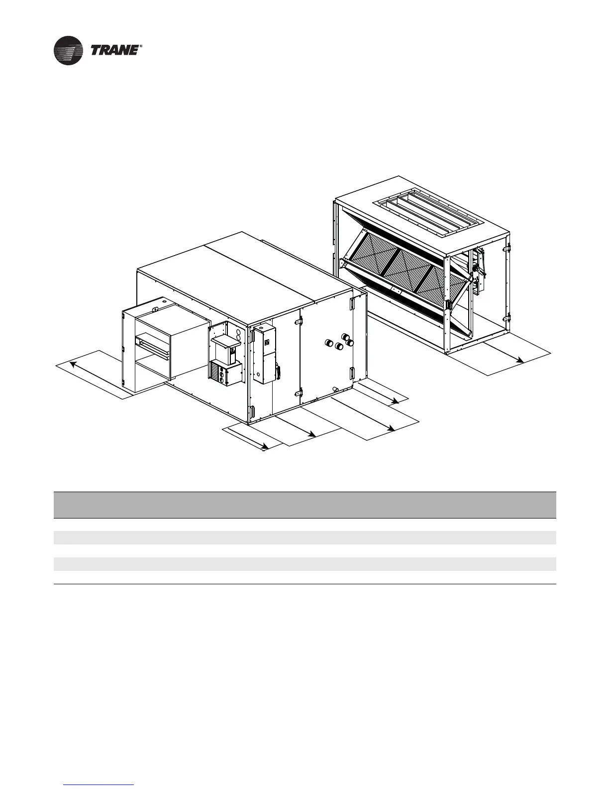
Service Clearances
Figure 2. Service clearances
A
B
C
D
E
A
Electric
heat
VFD
Control box
and fan
Coil
Mixing Box/Filter
Filter
Table 1. Service clearance dimensions (inches)
Letter Component
Unit Size
3 6 8 10 12 14 17 21 25 30
A Filter 40.00 44.00 42.00 42.00 40.00 45.00 45.00 45.00 51.00 51.00
B Coil 49.00 62.00 66.00 78.00 86.00 86.00 94.00 94.00 96.00 109.00
C Control Box/Fan 56.00 56.00 56.00 56.00 56.00 56.00 56.00 56.00 56.00 56.00
D VFD 48.00 48.00 48.00 48.00 48.00 48.00 48.00 48.00 48.00 48.00
E Electric Heat 45.00 40.00 39.00 35.00 31.00 32.00 27.00 30.00 28.00 23.00
Notes: At a minimum, the above clearance dimensions are recommended on one side of the unit for regular service and maintenance. Clearance on both
sides is recommended.
Refer to as-built submittal for locations of items such as filter access doors, coil, piping connections, motor locations, etc.
Sufficient clearance must be provided on all sides of unit for removal of access panels, plug panels, or section-to-section attachment brackets.
Clearance for starters, VFDs, or other high-voltage devices must be provided per NEC requirements.