Coil Piping and Connections
34 CLCH-SVX009A-EN
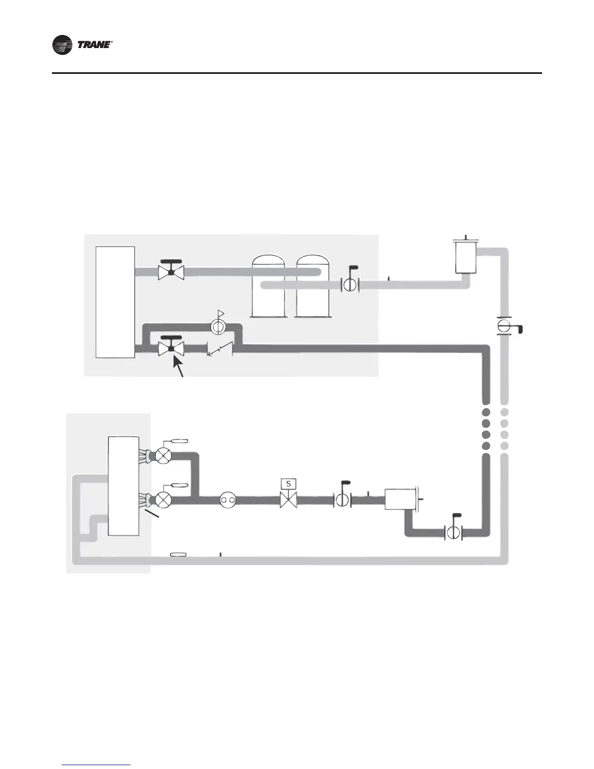
Refrigerant Coil Piping
Note: Refer to for information on handling refrigerants.
Figure 32 illustrates an example of a split-system
component arrangement. Use it to determine the proper,
relative sequence of the components in the refrigerant
lines that connect the condensing unit to an evaporator
coil. Refer to “Field-Installed Evaporator Piping
Examples,” p. 38 for more detailed schematics of
evaporator piping.
Figure 32. Example of placement for split-system components
Discharge
line
Manual
ball valve
Access
port
Filter
Access port
Access port
Filter drier
with access
port
Manual
angle valves
Check/relief valve
Condensing unit
Condenser and
sbucooler coil
Compressors
Liquid line
Access
port
Manual
ball valve
Solenoid
valve
Moisture-
indicating
sight glass
Expansion
valves
Evaporator coil
Distributor
Manual ball valve
Suction lineFrostat™ control
Manual
ball valve
Kit with sensor - X13790452010 SEN-01212
Kit with switch - X13100429010 THT 02442
Coil section
King valve access port