Installation
RT-SVX21N-EN 23
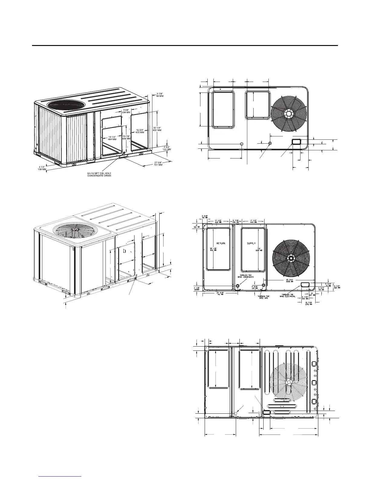
Figure 19, p. 23 to Figure 21, p. 23 illustrate the supply and
return air openings in a downflow configuration.
Elbows with turning vanes or splitters are recommended
to minimize air noise due to turbulence and to reduce static
pressure.
When attaching the ductwork to the unit, provide a water
tight flexible connector at the unit to prevent operating
sounds from transmitting through the ductwork.
All outdoor ductwork between the unit and the structure
should be weather proofed after installation is completed.
Figure 17. 4-6 ton high efficiency units, 7½-8½
(Microchannel) high efficiency unit and 6-10
ton standard efficiency units - horizontal
supply & return air openings
Figure 18. 10 ton high efficiency unit - horizontal supply
& return air openings
Supply
Return
3 7/8”
98 MM
9 3/8”
238 MM
19 1/4”
489 MM
16 3/4”
425 MM
4 3/4”
120 MM
32 1/4”
832 MM
27 5/8”
701 MM
Supply
Return
4 1/4”
108 MM
3/4-14 NPT DIA. HOLE
CONDENSATE DRAIN
32 1/4”
832 MM
Figure 19. 3-5 ton standard efficiency units&3tonhigh
efficiency units - Down flow supply & return air
openings w/ through-the-base utilities
Figure 20. 4-6 ton high efficiency units, 7½-8½
(Microchannel) high efficiency units and 6-10
ton standard efficiency units - down flow
supply & return air openings w/ through-the-
base utilities
Figure 21. 10 ton high efficiency unit - downflow supply
& return air openings w/ through-the-base
utilities
THROUGH
THE BASE GAS
THROUGH
THE BASE
ELECTRICAL
SUPPLY
RETURN
TBU CONDENSATE
3 5/8”
92 MM
14”
356 MM
9 1/4”
235 MM
15 1/2”
394 MM
4”
102 MM
24”
610 MM
16”
406 MM
27 9/16”
701 MM
4 3/16”
106 MM
4 9/16”
11 6 M M
23 1/2”
597 MM
2 13/16”
71 MM
6 1/2”
165 MM
3 11/16”
94 MM
4 7/8”
124 MM
5 1/16”
128 MM
9 15/16”
253 MM
Supply
Return
32 1/8”
816 MM
33”
MM
4”
102 MM
17 1/2”
444 MM
17 1/2”
444 MM
3 5/8”
92 MM
9 7/8”
251 MM
4 1/8”
104 MM
27 5/8”
701 MM
THROUGH THE
BASE CONDENSATE
4 5/8”
119 MM
THROUGH THE
BASE ELECTRICAL
51 13/16”
1316 MM
42 3/16”
1072 MM
5 7/8”
149 MM
6 3/8”
163 MM
2 3/4”
71 MM