Installation
30 RT-SVX21N-EN
120F,YHC120E andYHC072F-102F units secure the tab
on left side to the indoor coil block off with one of the
screws removed in step 2 and secure the right side of
the bracket with one of the screws removed from the
access panel. Refer to Figure 35, p. 29.
5. Using the remaining 2 screws removed in step 2,
secure the bottom bracket. Refer to Figure 34, p. 29.
Note: Larger diameter holes on bottom bracket line up
with the dimples on the rear panel.The smaller
diameter holes line up with the screw holes in the
rear panel.
Main Electrical Power
Requirements
Verify that the power supply complies with the unit
nameplate specifications.
• Inspect all control panel components; tighten any
loose connections.
• Connect properly sized and protected power supply
wiring to a field-supplied/installed disconnect switch
and to the main power terminal block (HTB1) in the unit
control panel.
• Install proper grounding wires to an earth ground.
Through-the-Base Gas
Installation
The gas supply line must extend 4⅝” above the base pan.
The “Through-the-Base Gas” kit is located in the Heat
Vestibule compartment.To gain access to the kit, remove
the Heat Compartment access panel.
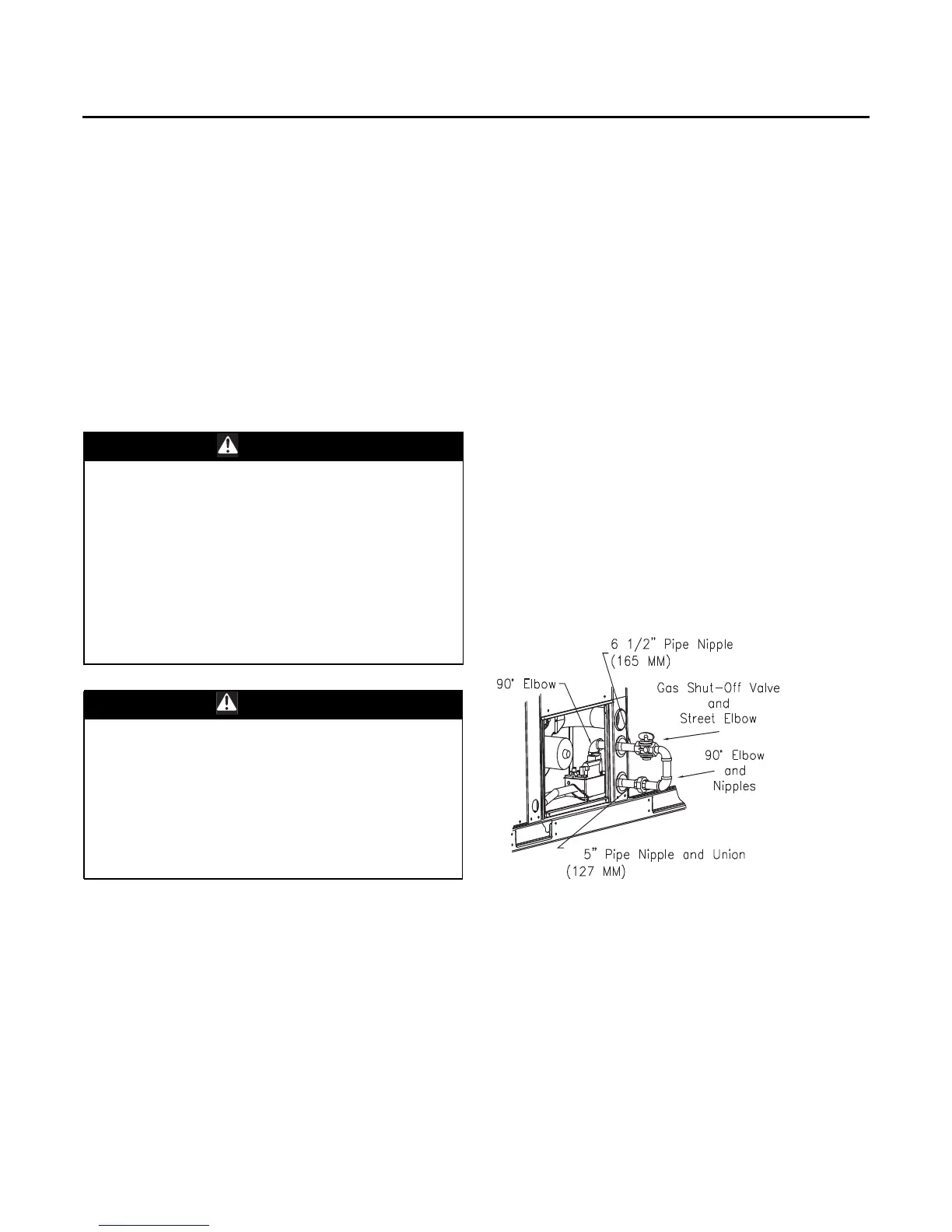
1. Remove the pipe assembly strapped to the manifold.
Unscrew 90° elbow from 6½” nipple and slide rubber
grommet off of nipple.
2. Remove the plastic plug from the hole in the center
post and insert the grommet removed from
6½” pipe nipple.
3. Using pipe sealant, attach the 90° elbow to the gas
supply line.
4. Disconnect the 5" pipe nipple and union from the
“Through-the-Base Gas” kit assembly.
5. Using pipe sealant, attach the 6½” nipple and gas
shutoff assembly to the 90° elbow on the gas supply
line.
6. Using pipe sealant, attach the 5" pipe nipple and union
to the street el attached to the gas valve.
7. Connect 5" pipe nipple and union to 6½” nipple and
gas shutoff assembly.
Requirements for Gas Heat
Note: The unit gas train and OptionalThrough-the-Base
Gas Shut-OffValve are rated at 1/2 PSIG maximum.
A pressure reducing regulator is recommended to
prevent this maximum from being exceeded.
These components must be isolated during field
gas piping test that exceed 1/2 PSIG. It is
recommended that the field piping be capped prior
to the unit gas train or OptionalThrough-the-Base
Gas Shut-Off Valve if present.
• Gas supply line properly sized and connected to the
unit gas train.
WARNING
Hazardous Voltage w/Capacitors!
Disconnect all electric power, including remote
disconnects and discharge all motor start/run
capacitors before servicing. Follow proper lockout/
tagout procedures to ensure the power cannot be
inadvertently energized. Verify with an appropriate
voltmeter that all capacitors have discharged. Failure to
disconnect power and discharge capacitors before
servicing could result in death or serious injury.
For additional information regarding the safe discharge
of capacitors, see PROD-SVB06A-EN
WARNING
Proper Field Wiring and Grounding
Required!
All field wiring MUST be performed by qualified
personnel. Improperly installed and grounded field
wiring poses FIRE and ELECTROCUTION hazards.To
avoid these hazards, you MUST follow requirements for
field wiring installation and grounding as described in
NEC and your local/state electrical codes. Failure to
follow code could result in death or serious injury.
Figure 36. Typical through-the-base gas installation