Installation
RT-SVX21N-EN 25
A Rigging illustration and Center-of-Gravity dimensional
data table is shown in Figure 15, p. 21. Refer to the typical
unit operating weights table before proceeding.
3. Remove all drill screws fastening wood protection to
metal base rail. Remove all screws securing wooden
protection to wooden top crate.
4. Remove WoodenTop Crate.
5. Rig the unit as shown in Figure 15, p. 21. Attach
adequate strength lifting slings to all four lifting
brackets in the unit base rail. Do not use cables, chains,
or slings except as shown.
6. Install a lifting bar, as shown in Figure 15, p. 21,to
protect the unit and to facilitate a uniform lift.The
minimum distance between the lifting hook and the
top of the unit should be 7 feet.
7. Test-lift the unit to ensure it is properly rigged and
balanced, make any necessary rigging adjustments.
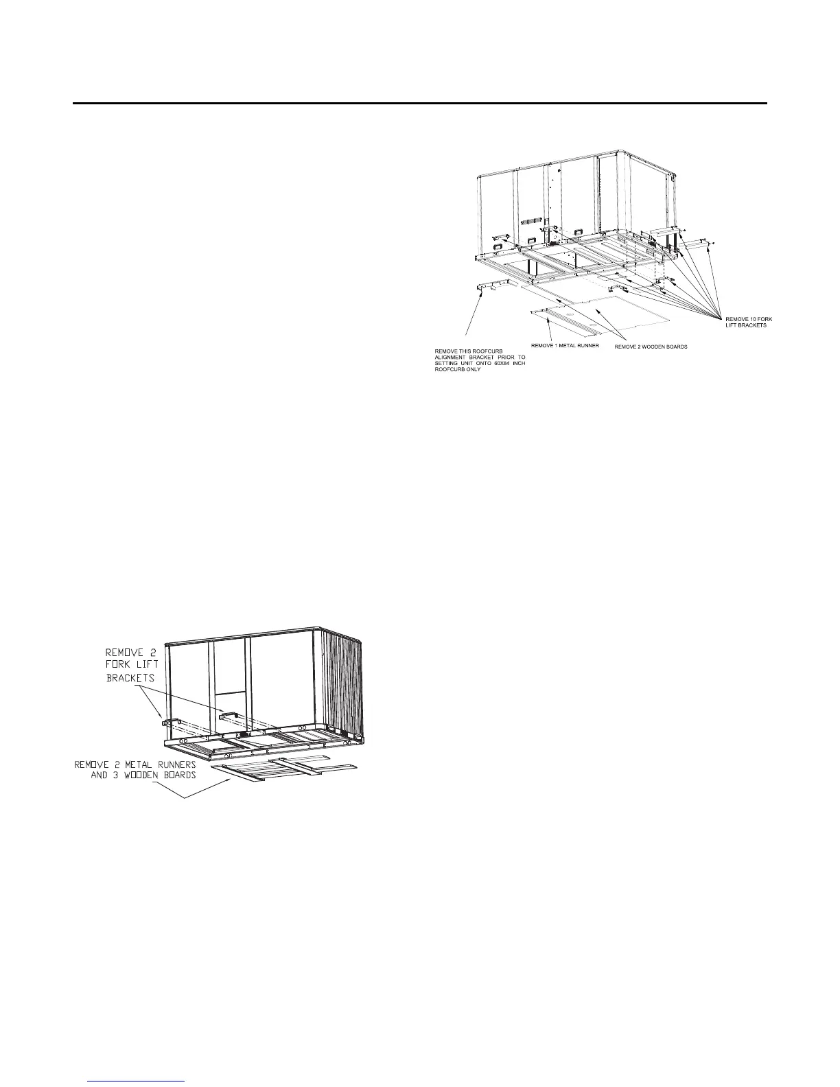
8. Lift the unit enough to allow the removal of base fork
pocket protection components as shown in the
following figures.When 10 ton high efficiency units are
installed on smaller existing roof curb (50"x 84") for
replacement applications, do not remove alignment
bracket.This bracket helps assure proper alignment of
duct openings.
9. Down flow units; align the base rail of the unit with the
curb rail while lowering the unit onto the curb. Make
sure that the gasket on the curb is not damaged while
positioning the unit.
General Unit Requirements
The checklist listed below is a summary of the steps
required to successfully install a commercial unit.This
checklist is intended to acquaint the installing personnel
with what is required in the installation process. It does not
replace the detailed instructions called out in the
applicable sections of this manual.
• Check the unit for shipping damage and material
shortage; file a freight claim and notify appropriate
sales representative.
• Verify correct model, options and voltage from unit
nameplate.
• Verify that the installation location of the unit will
provide the required clearance for proper operation.
• Assemble and install the roof curb (if applicable). Refer
to the latest edition of the curb installers guide that
ships with each curb kit.
• Fabricate and install ductwork; secure ductwork to
curb.
• Install pitch pocket for power supply through building
roof. (If applicable)
• Rigging the unit.
• Set the unit onto the curb; check for levelness.
• Ensure unit-to-curb seal is tight and without buckles or
cracks.
• Install and connect a condensate drain line to the
evaporator drain connection.
Note: Condensate Overflow Switch (if equipped) will not
work if unit is not leveled properly.
Factory Installed Economizer
• Ensure the economizer has been pulled out into the
operating position. Refer to the economizer installers
guide for proper position and setup.
• Install all access panels.
Figure 24. Fork pockets - all units except 10 ton high
efficiency units
Figure 25. Fork pockets - 10 ton high efficiency unit
NOTICE