Installation
34 RT-SVX21N-EN
Controls using DC Analog Input/Outputs
(Standard Low Voltage Multi
conductor Wire)
Before installing any connecting wiring between the unit
and components utilizing a DC analog input\output signal,
refer to “Unit Dimensions,” p. 13 for the electrical access
locations provided on the unit.
• Table 6, p. 34 lists the conductor sizing guidelines that
must be followed when interconnecting the DC binary
output devices and the system components utilizing a
DC analog input/output signal to the unit.
Note: Resistance in excess of 2.5 ohms per conductor can
cause deviations in the accuracy of the controls.
Note: Ensure that the wiring between controls and the
unit’s termination point does not exceed two and a
half (2.5) ohms/conductor for the length of the run.
• Do not run the electrical wires transporting DC signals
in or around conduit housing high voltage wires.
• Route low voltage wiring per illustrations on page 35.
DC Conductors
Table 5. Electromechanical thermostat 24V AC
conductors with electromechanical unit
Distance from Unit to Control Recommended Wire Size
0 - 30 feet 22 gauge
0 - 9.1 m .33 m2
31 - 50 feet 20 gauge
9.5 - 15.2 m .50m2
51 - 75 feet 18 gauge
15.5 - 22.9 m .75 m2
76 - 125 feet 16 gauge
23.1 - 38.1 m 1.3 m2
126 - 200 feet 14 gauge
38.4 - 60.9 m 2.0 m2
Table 6. Zone sensor module wiring
Distance from Unit to Control Recommended Wire Size
0 - 150 feet 22 gauge
0 - 45.7 m .33 mm2
151 - 240 feet 20 gauge
46 - 73.1 m .50 mm2
241 -385 feet 18 gauge
73.5 - 117.3 m .75 mm2
386 - 610 feet 16 gauge
117.7 - 185.9 m 1.3 mm2
611 - 970 feet 14 gauge
186.2 - 295.7 m 2.0 mm2
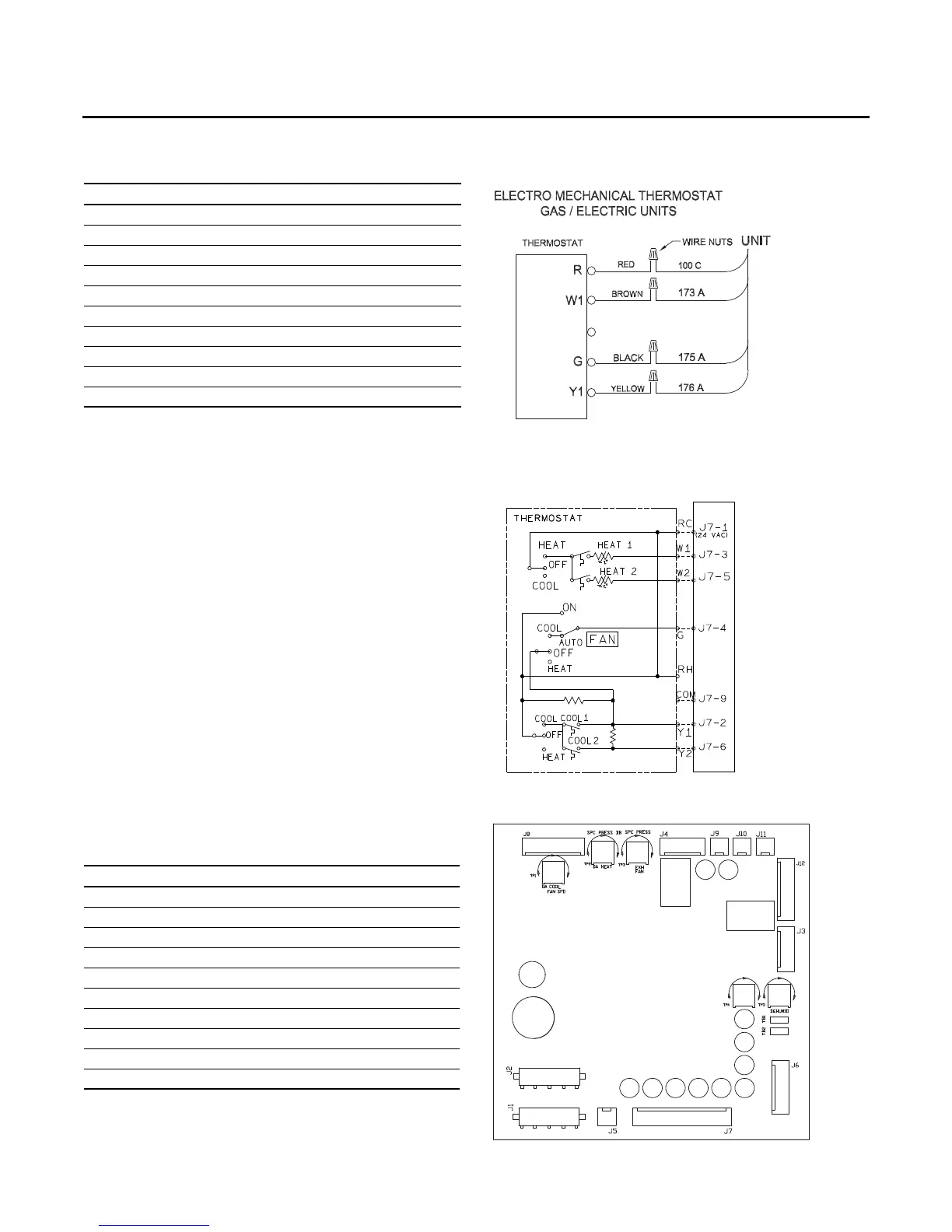
Figure 40. Typical field wiring diagrams for
electromechanical
Figure 41. ReliaTel™ conventional thermostat field
wiring diagrams
Figure 42. ReliaTel™ options module
RTRM