0221
49
7. ATEX
7. ATEX
7.1 Informazioni generali
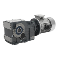
I riduttori Transtecno CMG, CMB, ATS, CM, CMP, CMM,
PU, PX, CMPU, FT, FT030/050, RH030/050, POK, CL,
CWT, VAM, ITH, ITB, ITS possono essere richiesti in fase di
ordine rispondenti alla normative ATEX:
Gruppo II, categoria 3 G Ex h IIB T4 Gc
Gruppo II, categoria 3 D Ex h IIIB T=135°C.
Al momento della ricezione verificare che la targhetta cor-
risponda a quella mostrata nel capitolo “2) Stato di fornitura”.
Attenersi a tutte le informazioni e le istruzioni riportate su
ogni capitolo di questo manuale.
7.2 Installazione
Prima dell’installazione dei riduttori ATEX è necessario con-
trollare, oltre alle precedenti istruzioni, anche:
● che nessuna delle pareti del riduttore mostri danni alla ver-
niciatura o a qualunque parte o componente del riduttore.
● che non ci siano residui di imballaggi aggrappati al riduttore
● che non vi siano tracce di corrosione, perdite di lubrificante
o sporco su tutte le superfici e sui componenti del riduttore.
● che la targhetta sia ben visibile e non danneggiata e che
risponda alla normative ATEX desiderata
● che questa documentazione risulti sempre leggibile e nelle
vicinanze del riduttore
In caso contrario: non installare e contattare Transtecno
srl
Se i precedenti punti sono rispettati allora è necessario
provvedere a:
● Ingrassare con lubrificanti idonei tutti gli accoppiamenti tra
parti in acciaio a contatto tra loro, sia striscianti che fissi, con
lubrificanti appositi
● Verniciare tutte le superfici dei riduttori lavorate e non ver-
niciate che non sono state utilizzate.
● Montare il riduttore ( ove previsto ) solo nella posizione di
montaggio specificata nella targhetta.
● Prevedere sufficiente spazio libero nell’intorno del riduttore
e conseguente passaggio di aria in modo da evitare accumu-
lo di calore o surriscaldamento
● Non convogliare aria calda di scarico da altri apparati al
riduttore
7.3 Messa in servizio
Oltre alle istruzioni del capitolo “5) Messa in servizio” è
necessario procedere come segue:
● Dopo alcune ore di funzionamento a regime accertarsi che
il gruppo non superi la temperature superficiale specificata in
targhetta nel suo punto più caldo; in caso contrario fermare il
gruppo e contattare il nostro servizio tecnico.
● Accertarsi che la temperature dell’ambiente non ecceda i
limiti di utilizzo del riduttore.
7.1 General information
Transtecno CMG, CMB, ATS, CM, CMP, CMM, PU, PX,
CMPU, FT, FT030/050, RH030/050, POK, CL, CWT, VAM,
ITH, ITB, and ITS gearmotors that comply with the following
ATEX Regulations can be requested when ordering:
Group II, category 3 G Ex h IIB T4 Gc
Group II, category 3 D Ex h IIIB T=135°C.
On receipt, check that the nameplate matches that shown in
Section “2) Condition on Supply”.
Take note of all of the information and comply with all of the
instructions contained in each Section of this manual.
7.2 Installation
7.3 Start-up
In addition to following the instructions in Section “5) Putting
into Service”:
● After a few hours’ operation at full speed, ensure that the
unit does not exceed the surface temperature, stated on the
nameplate, at its hottest point; if it does, switch off the unit
and contact our Technical Department.
● Ensure that the ambient temperature does not exceed the
gearmotor’s operating limits.
Before installing ATEX gearmotors, in addition to following
the above instructions, you must also check:
● that none of the gearmotor walls is damaged as regards
paintwork or any other part or component of the gearmotor;
● that no remnants of packaging are attached to the gear-
motor;
● that there are no traces of corrosion, oil leaks or dirt on any
of the gearmotor’s surfaces or components;
● that the nameplate is clearly visible and undamaged and
complies with the required ATEX Regulations;
● that this documentation is always legible and kept near the
gearmotor.
Otherwise: do not install and contact Transtecno srl
If the above conditions have been met, then the following
actions must be performed:
● Using the appropriate lubricants, grease all of the connec-
tions between steel parts that come into contact with each
other, both sliding and fixed.
● Paint all of the gearmotor’s machined and unpainted sur-
faces that have not been used.
● Mount the gearmotor (if applicable) only in the mounting
position stated in the nameplate.
● Allow sufficient space around the gearmotor to enable the
air to flow freely so as to prevent the build-up of heat or over-
heating
● Do not convey hot exhaust air from other devices to the