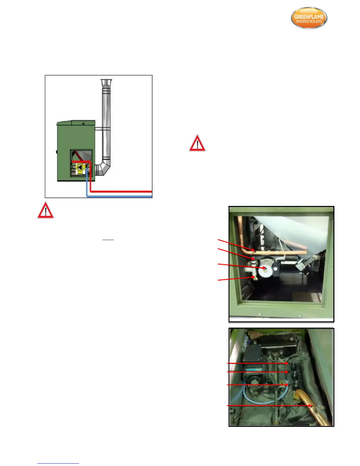
4.5 Water Connections
The diagram below indicates the plumbing connections at
the rear of the boiler. The return connection is factory fitted
with a 25/6 standard pump.
Incorrectly sized expansion vessel will invalidate the
warranty. A minimum 18 litre expansion vessel is
recommended for the boiler PLUS additional expansion for
the heating and domestic hot water system.
The boiler can be plumbed into either an open vented
system (the maximum static head of water permissible is 90
ft. (27.44 metres) or a sealed system. If plumbed into a
sealed system an appropriately sized expansion vessel should
be used and installed as per manufacturer’s instructions. The
expansion vessel should be sized based on the water
capacity in the boiler and the water in the entire heating
system.
The pump is on the return pipe work just before the boiler. It
is recommended that a by-pass pipe between the flow and
return is used with a valve to regulate the temperature of
the water returning to the boiler. Also, the system designer
should ensure that there is adequate provision in the system
for heat dissipation from the boiler during the shut-down /
extinguishing phase. An automatic air vent and pressure
relief valve should be piped to a drain to prevent injury to
the User or Service Technicians if it is activated. All unused
connections should be sealed with blanking plugs.
A non-return valve should be fitted to prevent back-
siphonage.
Once the plumbing has been completed the system should
be fully flushed to clear any debris which may have become
lodged in the pipe work. The system should generally be
filled from the lowest point on the system to force any air to
the highest point where it can be vented. The flow pipe on
the boiler is fitted with a manual air vent for venting air from
the boiler. The system must then be filled and the pump can
be run continuously for a few hours to completely de-aerate
the system. Hold the ESC button on the controller for 3
seconds to activate the pump. Repeat the procedure to turn
it off. Only when the system has been fully vented can the
boiler be commissioned.
The installation and the design of the central heating system
must be in accordance with BS EN 14336:2004: Heating
systems in Buildings. Installation and commissioning of water
based systems. BS EN 12828:2003; Heating Systems in
Buildings. Design of water based heating systems. BS EN
12831:2003: Heating Systems in Buildings. Method for
calculation of the design heat load.
Always ensure that all connections are making a watertight
seal.
If a buffer probe is being used to control the boiler then no
other external controls can be used and P35 should set to 5
in the system menu under default settings.
If the system is a Y plan or S plan and external controls will
be used to control the boiler then P35 should be set to 1.