page -10
Select the anti-legionella function by turning selector 4 to ON (see "Electrical Diagram").
4.8.- Installing the SRFC2/EV Underfloor Heating Kit (Optional)
The procedure for suitably connecting the SRFC2/EV Underfloor Heating Kit to the TRO
Evolution System boiler is as follows:
- Unplug the boiler from the mains.
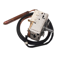
- Connect a flow temperature sensor (supplied with the kit) to sensor terminal strip J3
(terminals 15 and 16), first removing the resistance (Rr) supplied by default (see “Electrical
Connection Diagram").
- Fit the temperature sensor bulb according to the instructions enclosed with the kit.
- Connect the heating pump to supply terminal strip J2 on the circuit 1 pump connection
(pump BC
1
; terminals N and 7) (see “Electrical Connection Diagram").
- Connect the PWM
C
cable to sensor terminal strip J3 (terminals 13 and 14) (see “Electrical
Connection Diagram").
- Connect the 3-way mixer valve motor to supply terminal strip J2 (terminals N, 8 (+) and 9
(-)) (see “Electrical Connection Diagram").
For correct hydraulic installation, carefully follow the assembly and connection instructions
enclosed with the SRFC2/EV kit.
4.9.- Heating circuit 2 (Optional)
All the models in the TRO Evolution System range of boilers are supplied with a circulation
pump connected to heating circuit 1 (BC1). In addition to this circuit, all the models are
designed to control a second heating circulation pump in a second heating circuit (circuit 2,
BC
2
).
The hydraulic installation of heating circuit 2 should be made using the optional flow circuit
(IC') on the rear of the boiler (see "Diagrams and Measurements"). If there is an SRFC2/EV
underfloor heating kit connected to the optional flow IC', heating circuit 2 should be
connected at the additional sockets provided in the kit (on the boiler T-connectors).
The circulation pump installed in heating circuit 2 must be electrically connected between
terminals N and 6 on the supply connector block J2 (see “Electrical Connection Diagram").