page -38
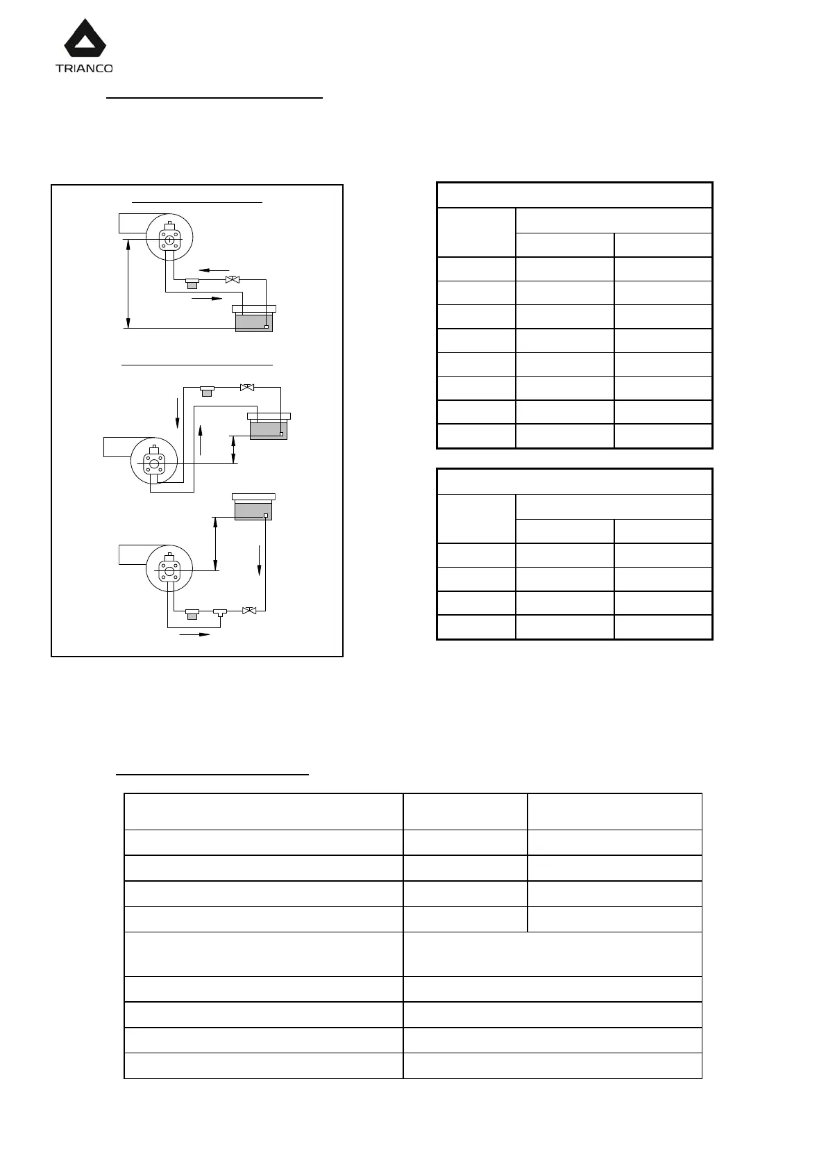
24.9.- Oil supply piping diagrams
The diagrams and tables below correspond to installations without reductions and with a
perfect hydraulic seal. It is recommended to use copper pipes. A pressure drop of 0.4 bar (30
cmHg) must not be exceeded.
Intake installation
H Pipe length
(m) int. 8 mm. int. 10 mm.
0.0 25 60
0.5 21 50
1.0 18 44
1.5 15 38
2.0 12 26
2.5 10 26
3.0 8 20
3.5 6 16
Charging installation
H Pipe length
(m) int. 8 mm. int. 10 mm.
0.5 10 20
1,0 20 40
1.5 40 80
2.0 60 100
WARNING: Check periodically the flexible pipes conditions. Using kerosene, they have to be
replaced at least every 2 years.
24.10.- Technical specifications
MODEL D-3 D-4
Minimum consumption Kg/h
1.5 2.3
Maximum consumption Kg/h
3 4.65
Minimum power kW
17.7 27.2
Maximum power kW
35.5 55.2
Fuel
Gas oil 35 Sec max. Viscosity 6 mm
2
/s at
20ºC Kerosene 28 Sec
Motor power at 2800 r.p.m. W
90-110
Adjustment type
On/Off
Electric current
220 V - 50 Hz
Weight Kg
12.5
Intake installation
H
Charging installation
H
H