EasyManua.ls Logo

Trilogy Orator - GPI O Connector

Trilogy Orator
37 pages
Print Icon
To Next Page IconTo Next Page
To Previous Page IconTo Previous Page
Loading...
Orator Installation Guide
Issue 1Trilogy Broadcast Limited Page 17 of 37
Orator
3.3.6 GPI O Connector
Connector: 25 way D type fixed socket.
Pin Number Function
1 GROUND
14 Output 1+
2 Output 1-
15 Output 2+
3 Output 2-
16 Output 3+
4 Output 3-
17 Output 4+
5 Output 4-
18 Output 5+
6 Output 5-
19 Output 6+
7 Output 6-
20 Output 7+
8 Output 7-
21 Output 8+
9 Output 8-
22 Input 1
10 Input 2
23 Input 3
11 Input 4
24 Input 5
12 Input 6
25 Input 7
13 Input 8
The circuit below shows suggested
wiring for Output 1 of the Orator
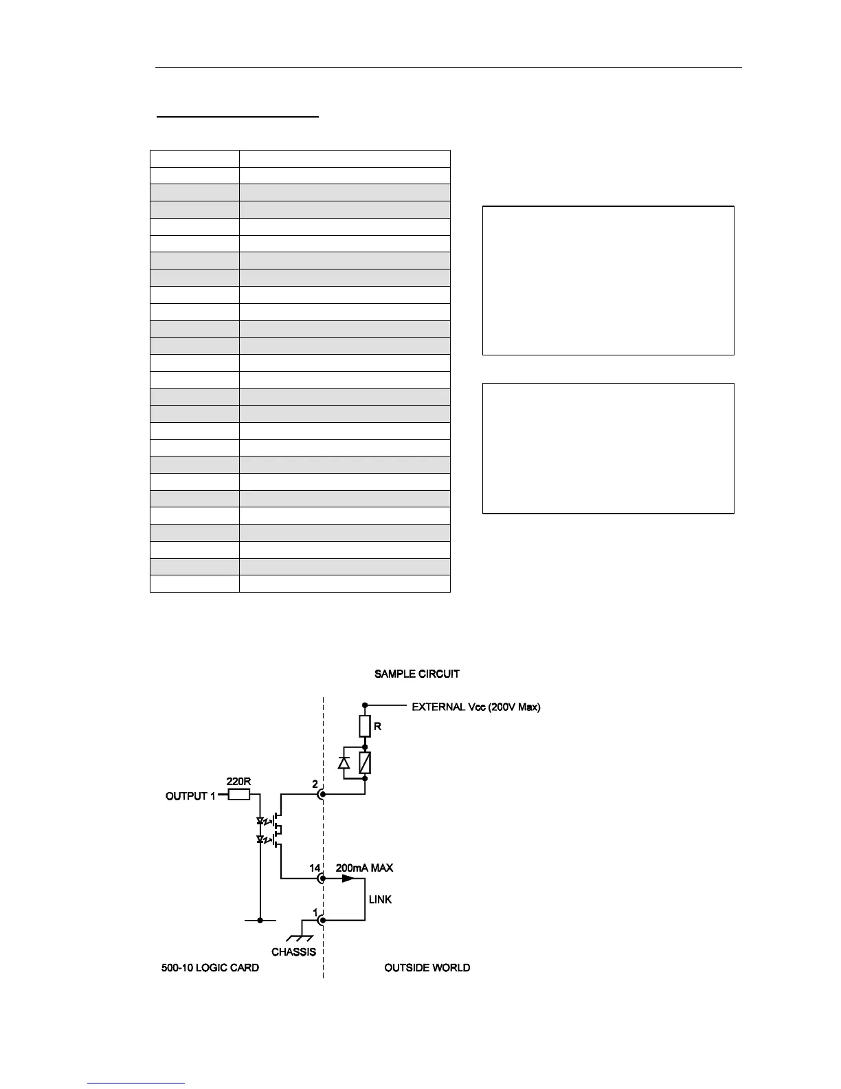
Logic facilities Maximum current
through the output stage must be
limited to 200mA and the maximum
permitted external voltage is +200V.
If these limits are exceeded, the
card may be damaged.
To activate a logic input, connect the
relevant logic input pin to ground. A
typical example of the external
circuitry for the logic outputs is
shown below.