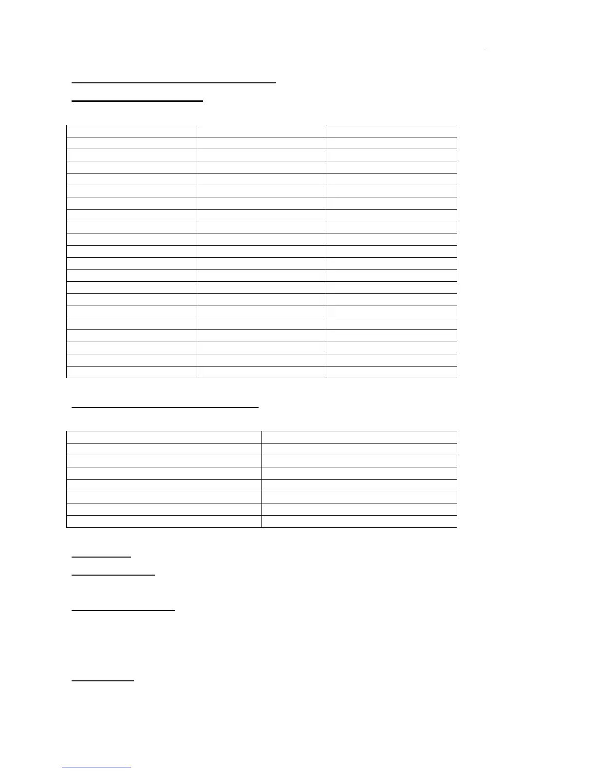
5.4.1 ISDN Interface Connector Pin-Outs
5.4.1.1 Bearer 1 & Bearer 2
Audio Input XLR pin 1 Ground
XLR pin 2 Balanced input 1
XLR pin 3 Balanced input 2
Audio output XLR pin 1 Ground
XLR pin 2 Balanced output 1
XLR pin 3 Balanced output 2
15 pin D-type Pin 1 AUTO control input
Pin 2 DROP control input
Pin 3 +5VDC
Pin 4 D8 DTMF output
Pin 5 D4 DTMF output
Pin 6 D2 DTMF output
Pin 7 D1 DTMF output
Pin 8 Not connected
Pin 9 SIEZE control input
Pin 10 Ground
Pin 11 Line Mode output
Pin 12 Automode output
Pin 13 DTMF data valid
Pin 14 Not connected
Pin 15 Not connected
5.4.1.2 ISDN Interface RJ45 Connector
Pin1 Not connected
Pin 2 Not connected
Pin 3 Tx to network A/Rx from terminal A
Pin 4 Rx from network A/Tx to terminal A
Pin 5 Rx from network B/Tx terminal B
Pin 6 Tx to network b/Rx from terminal B
Pin 7 Not connected
Pin 8 Not connected
5.4.2 Notes
5.4.2.1 Com Port
This feature will be supported in future software releases.
5.4.2.2 Remote Ports
Each input is the cathode of the LED on an opto-isolator. The anode is connected through a
470R resistor to +5VDC. Therefore to activate a control input, short the pin to ground, i.e. pin
10. Each output is the open collector of a ULN2003 driver chip. Therefore connect the pin
through load to +5VDC.
5.4.2.3 RJ45
This is the ISDN 2 connector. This must only be connected to an approved ISDN 2
connection or serious damage may occur.