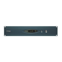
4.3 500-41 Series Desktop Panels
These differ from the other control panels since the matrix link is via a RJ-45 connector. The
pin-out is given in the table below. To make a cable, use a 9-way plug at the matrix end. The
following wiring applies to panels marked "Mod State 2" and later. Earlier panels had pins 4
and 6 transposed internally, with corresponding changes to the interconnecting cable. The
later wiring allows operation over longer lengths of structured cabling.
RJ-45
Pin
Function 9 way D Free Plug
at matrix end
1 Panel Data out + 6
2 Panel Data out -
Pair 1
2
3 Panel Data In + 7
6 Panel Data In -
Pair 2
3
5 Panel Audio out + 8
4 Panel Audio out -
Pair 3
4
7 Panel Audio in + 9
8 Panel Audio in -
Pair 4
5
Cable Screen 1
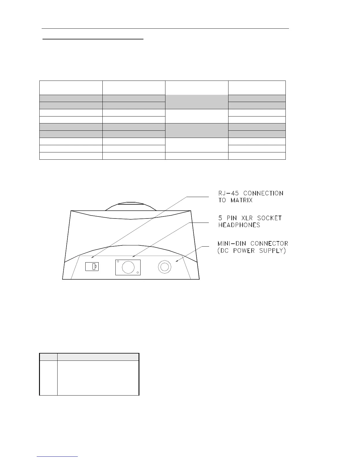
The next diagram shows a rear view of the desktop panel.
For connection via structured cabling, RJ45 to 9 way D adaptors are available from
electronic distributors. See section 4.5 for further details.
The desktop panel is DC powered from a mains power supply unit connected via the mini
DIN connector on the rear. The only remaining user connection is to the Headset connector
on the rear of the desktop. The pin-out is:
Headset - 5 Pin XLR Fixed Socket
(rear panel)
Pin Function
1 Mic IN (Screen)
2 Mic IN
3 Headset Gnd
4 Headset Out
5 Headset Out