GPIO (Local logic in and out) - 9D Fixed Socket
Pin Function Notes
1 Ground
2 Logic Input 1
3 Logic Input 2
4 Logic 2 Out Common
5 Internal +5V (Out) Protected with series 44R & 1N4002 diode.
6 Logic Output 1
7 Logic 1 Out Common
8 Logic Output 2
9 Logic Input +VCC NB Pin 9 may be driven by external voltage (With
dropper resistor if greater than 5V), or by internal +5V
via pin 5.
Audio I/O – 15D Fixed Socket
Pin Function Notes
1 Slave Mic Input Line level, un-balanced
2 +15V Out (for slave mic panel) NOT protected!
3 Clean Mic Out + Line level, balanced, pair with 11
4 Ext CUT Input (for slave mic panel) Parallel function to front panel Cut
Switch. Ground to activate
5 Chassis Ground
6 No connection
7 External Input to LS Amp - Line level, balanced, pair with 14
8 Matrix Audio Input to Panel / parallel output - Line level, balanced, pair with 15
9 Ext Mic Cut output (to slave panel) Normally grounded. O/P is open
circuit when front panel cut
selected.
10 -15V Out (for Slave mic panel) NOT protected
11 Clean Mic Out - Line level, balanced, pair with 3
12 Mic Ground
13 Loudspeaker Output 8 ohm loudspeaker
14 External Input to LS Amp + Line level, balanced, pair with 7
15 Matrix Audio Input to Panel / parallel output + Line level, balanced, pair with 8
NB 15V supplies are also used to derive 12V for panel. (Thermally Fused @ 0.7A)
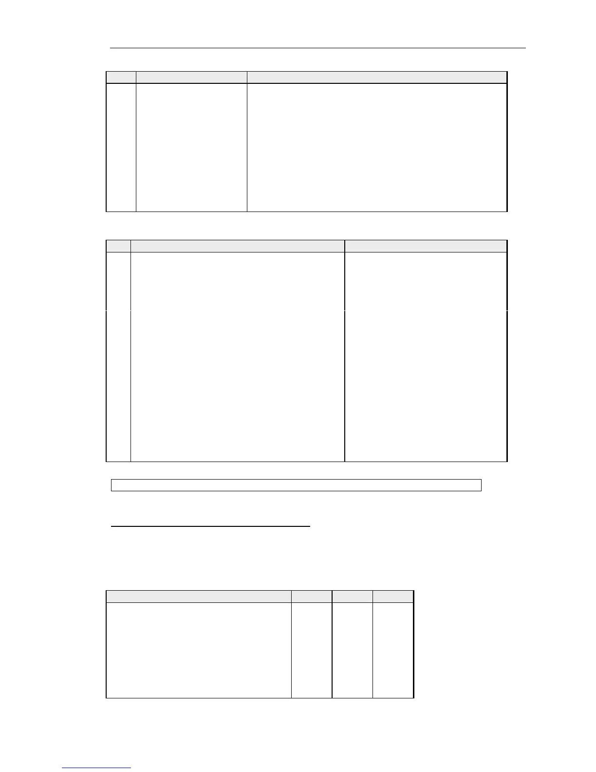
4.1.3 500-30 Series DIP Switch Settings
Within the panel a series of DIP switches determine the correct panel type. These are
factory set and are included for reference in Appendix 1.
A further set of DIP switches are user accessible at the top side of the panel and control the
action of the front panel CUT switch.
Cut Switch Action DIP 1 DIP 2 DIP 3
No action OFF OFF OFF
Changeover to HSet MIC ON OFF OFF
LS cut OFF ON OFF
Changeover to HSet MIC and LS cut ON ON OFF
MIC cut OFF OFF ON
Changeover to HSet MIC and MIC cut ON OFF ON
LS cut and MIC cut OFF ON ON
Everything ON ON ON