Module Operation and Features
(38246-01/38847-01) — Section 4
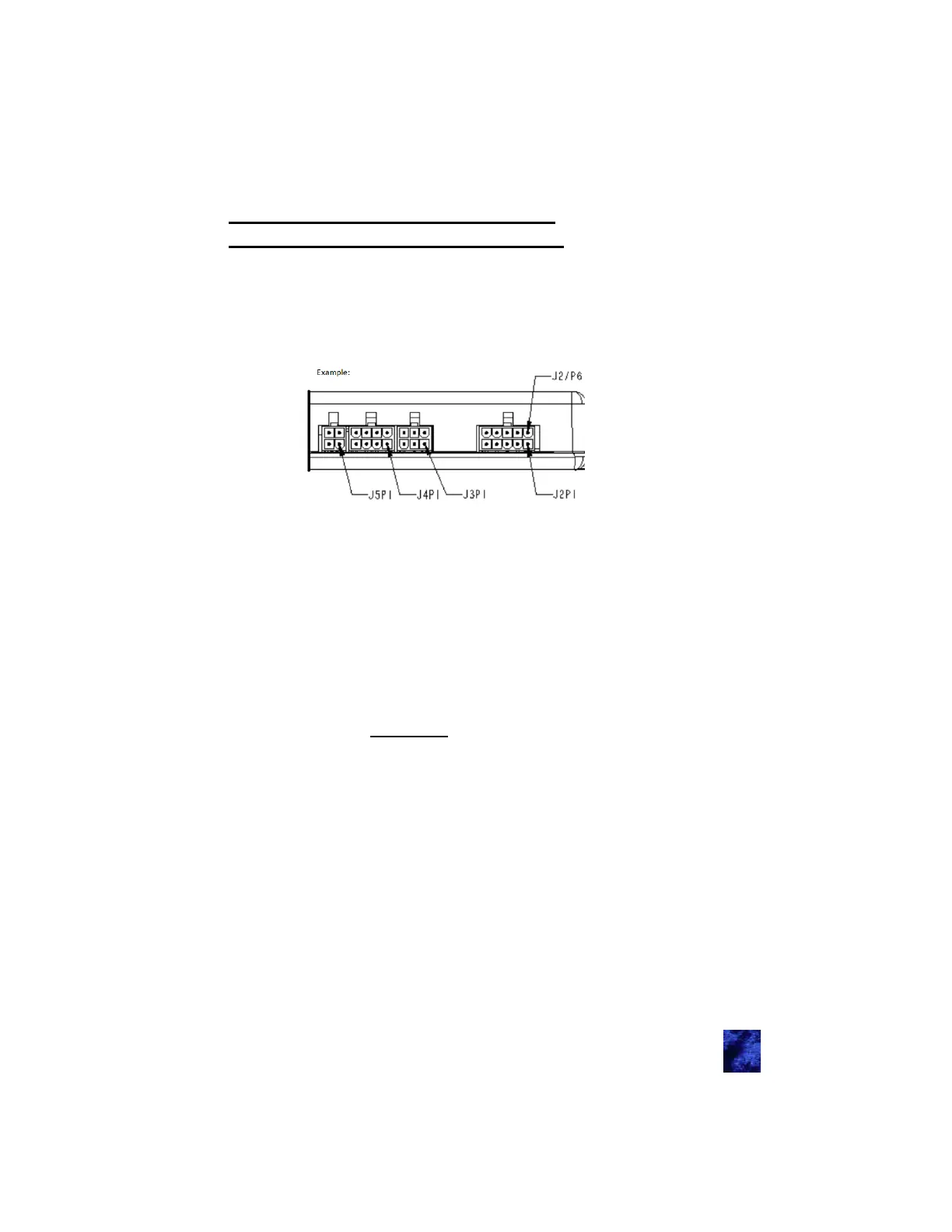
Module Connectors and Functions
If you look at the TriMark IO module with the label pointed up, the
numbering system is bottom right to top left (opposite of how you read).
(see diagram below)
For all inputs:
(-) indicates that the inputs normally floats (no predetermined
voltage to input) unless a ground signal is placed to activate pin.
(+) indicates that the inputs normally floats (no predetermined
voltage to input) unless a 12V signal is placed to activate pin.
(+/-) indicates that the inputs normally floats (no predetermined
voltage to input) the voltage is the opposite of J2P7 to activate
(selectable).
For all outputs:
(-) upon activation a 500mA ground path will be activated.
(Relay 20A) a momentary path that is normally ground will be
vehicle power (lock unlock doors, extra).
(Relay 30A) Bank D has multiple pins to allow higher currents
through these connectors. The four pins to allow this higher
current are J1P5, J1P6, J1P17, and J1P18 described on the next
page.
Note: Most fuses are based on wire gauges. Fuses should be gauged
accordingly.
For all Signals:
Follow CAN/J1939 protocol (see acronyms)
For all Antennas:
An AC signal (for communications)
14