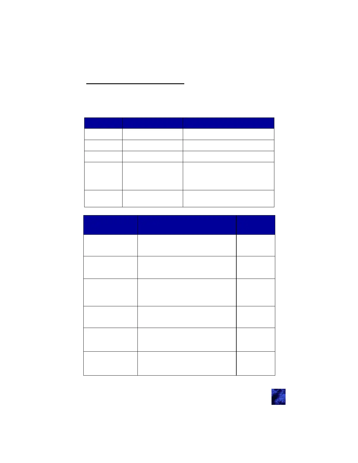
Green LED Red LED Software Mode / Current State
On On Internal programming occurring
On Off Normal full-power operation
Off Off No power
Off
Blink X times, then wait
1.5 seconds and repeat
Run-time error detected. The value of
“S” indicates the exact error that is
detected. The table below give more
information of each possible error
Fast blink
(5 time/second)
Fast blink
(5 time/second)
Pairing FOBs mode
Appendix D: Error Codes
There is a red and green LED located to the left of the programming
port. This is visually shown in the Module Connectors and Functions
under Connector Locations. The purpose of these LEDs is to indicate
the mode the system is in.
Fault Exact Error
Errors
Blinks “X”
CAN error (continue to
Appendix D: Trouble-
shooting
No CAN Traffic for 2 seconds while vehi-
cle is in gear
1
CAN error (continue to
Appendix D: Trouble-
shooting
A CAN line is above 5VDC 2
LF receiver not re-
sponding (continue to
Appendix D: Trouble-
shooting
LF Module Communication Error 3
Door locks relays not
responding
I/O Expander Module Communication
Error
4
CAN error (continue to
Appendix D: Trouble-
shooting
CAN Bus Data Erratic No CAN Traffic for
5 seconds
5
Damaged IC chips
(continue to Appendix
D: Troubleshooting
EEPROM Read/Write Error 6
27