10
Dual control built-in thermostatic mixer shower
BUILT-IN FITTING
The following are typical thicknesses and are
given as a guide only:
Tile 6 − 10mm
Adhesive 2 − 3mm
Plasterboard 9.5 − 12.5mm
Plaster nish 2 − 3mm
Maximum tile thickness to be 10mm.
When installing into a stud partition or other
hollow wall structure, the installer may wish to
consider building rear supports or other options
for tting the mounting plate. Such options are
beyond the scope of this guide.
Use the cover plate or tiling shroud (if supplied)
as a template when cutting the opening for
installing the shower into a solid wall, stud
partition or hollow wall structure.
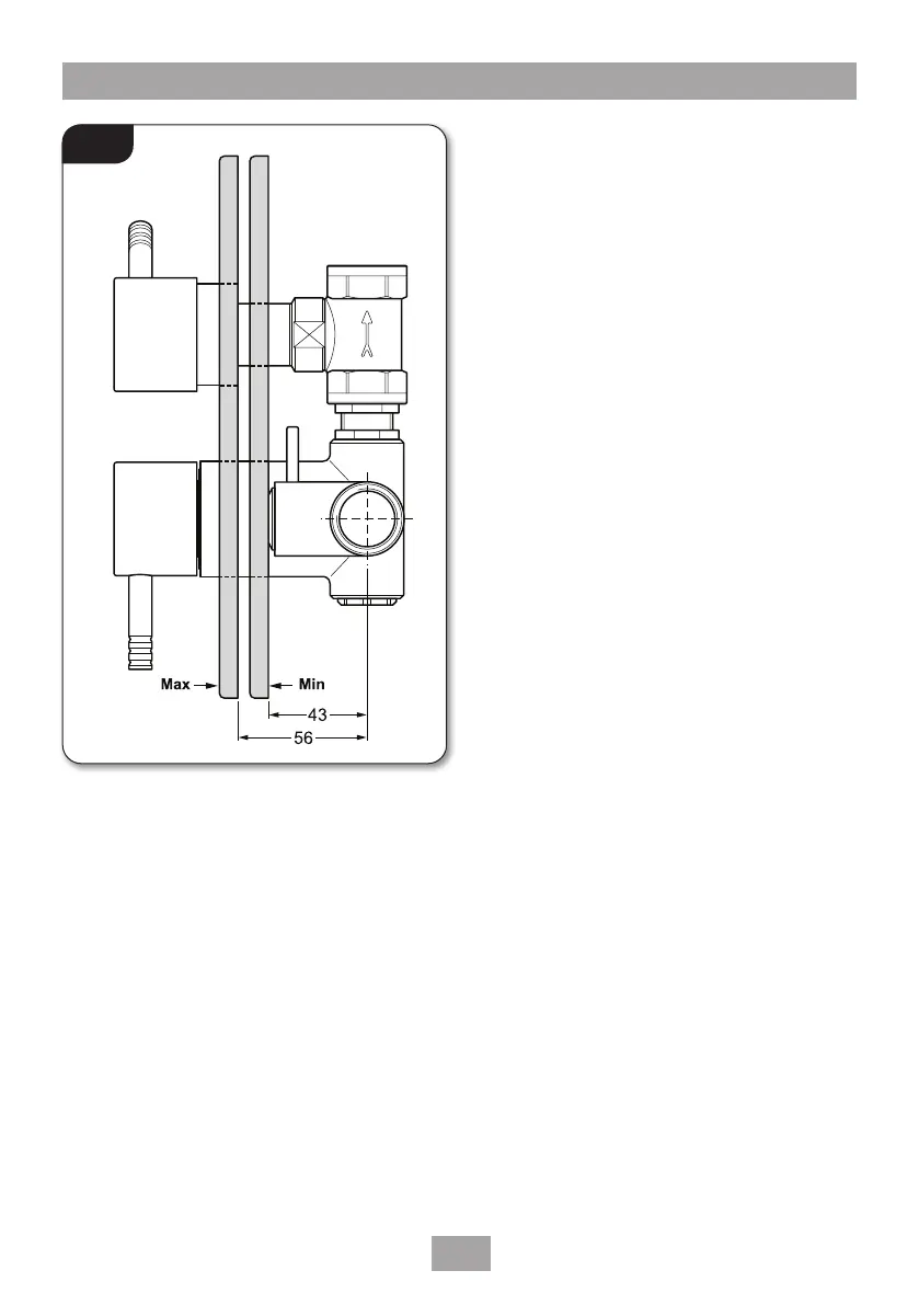
The building-in depth for the mounting plate
from the plaster nish is given in g.9 but this is
dependent upon tile and adhesive thicknesses.
The inlet elbows allow for either rising, falling or
rear entry hot and cold water supplies.
NOTE: To ease future requirements for
cleaning and maintenance of the unit, it is
advisable to route both the incoming and
outgoing pipework from the same direction.
Access to the integral strainers will also be
improved with this layout.
Installation in a Solid Wall
Decide on the shower position and determine
whether the hot and cold water supplies will
enter the shower from top (falling) or bottom
(rising) or rear.
As a guide for the size of hole, it should be large
enough to accept the valve complete with the
inlet and outlet ttings and also allow access for
connection to the pipework.
Remove the plaster and brickwork to the required
depth and chase out any additional areas of the
wall to give access to the pipework to and from
the valve plus any outlet ttings. Note that the
valve body requires a deeper recess than the inlet
and outlet ttings.
Fig.9