12
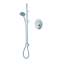
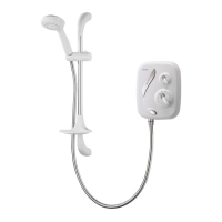
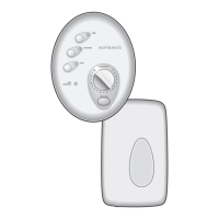
Dual control built-in thermostatic mixer shower
FITTING THE SHOWER
Mark the position of two locating screws.
Drill and plug the holes. Use an appropriate
masonry drill, but if the wall is plasterboard or a
soft building block, use special wall plugs and a
suitable drill bit.
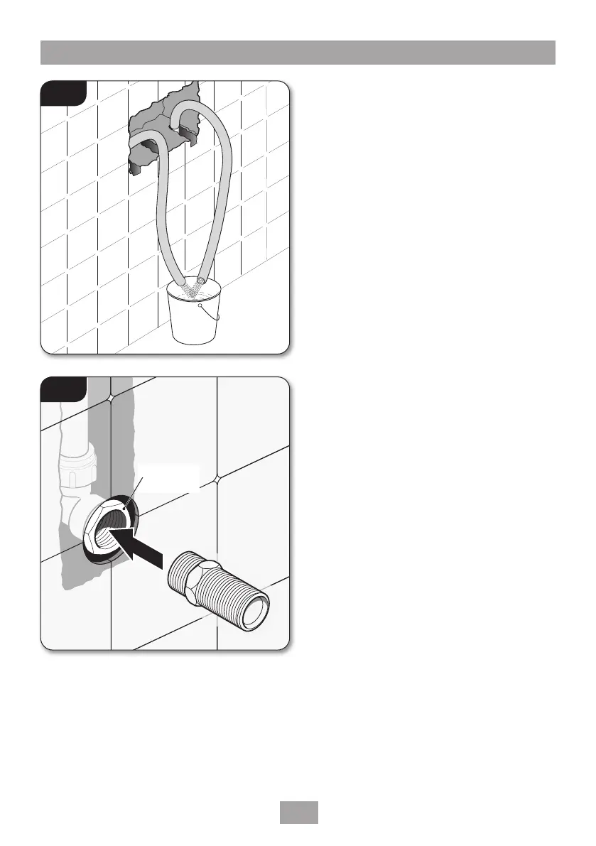
IMPORTANT: Make sure that all supply
pipework has been ushed through before
tting the mixer (g.11).
Connect the hot water supply to the inlet marked
HOT, ‘H’ or red/orange label and connect the cold
water supply to the inlet marked COLD, ‘C’ or
blue label.
Tighten all compression ttings.
Secure the mixer to the wall.
FITTING THE BULKHEAD PIPEWORK
Complete the outlet pipework ending in a 15mm
x ½” BSP female thread elbow (g.12).
NOTE: This tting is not supplied as variations
in installations require the selection of a
suitable solder or compression tting.
Screw the supplied male-thread connector into
the female tting (g.13) using PTFE tape to
give a watertight joint.
NOTE: The male-thread connector supplied
has a shoulder. If tting into a ush wall, make
an additional 8mm allowance for this shoulder
at the nished surface. The connector can be
cut to size if required.
The threaded connector should protrude from the
nished wall surface between 8mm and 13mm.
LEAK TESTING
Direct the outlet of the shower to waste. Open
the isolating valves to the shower and check for
leaks. Remedy any leaks found.
Fig.11
8mm − 13mm
Finished surface
Fig.12
Appropriate
tting