RUNNING ADJUSTMENTS
ADJUSTMENT
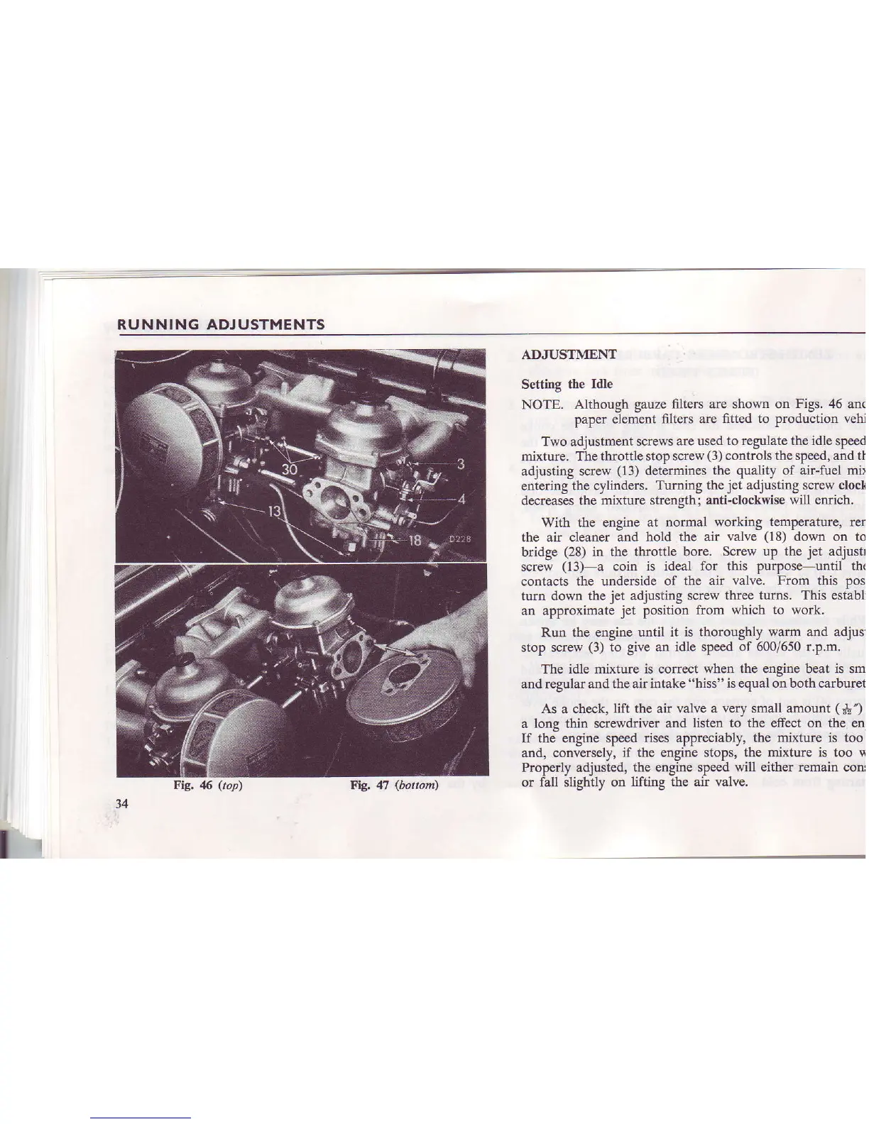
Setting the
Idle
NOTE.
Although gauze
fi1te6 are shown on
Figs.
46 ana
paper element
filters are
fitted to
production
vehi
Two adjustment
screws arc used
to regulate the idle
speed
mixture. The throttle stop screw
(3)
controls the speed, and tl
adjusting screw
(13)
determines lhe quality of air-fuel
mi>
enlerjng the cylinders.
Turning
the
jet
adjusting screw clock
decreases
the mixture strength; anti-clockwise
will enrich,
With the engine
at nomal working
temperature,
ren
the
air
cleaner and hold the air
valve
(18)
down on to
bridge
(28)
in the throttle bore.
Screw up the
jet
adjustl
screw
(13)
a coin
is ideal for this purpose-until th(
contacts
the undenide of the air
valve. From this
pos
turn dow[ the
jet
adjusting
screw three tums. This establi
an approximate
jet
position from
which to work.
Run the engine
until it is thoroughly
warm
and adjusl
stop screw
(3)
to give an idle speed
of 600/650 r.p.m.
The idle
mixture is corlect when the engine beat is sm
and regular and the air intake
"hiss"
is equal o--n both carburet
As
a
check, lift the air
valve a very small amount
(j!)
a long thin screwdriver
and listen to the effect oll the eni
If
the
engine
speed rises appreciably,
the mixture is too
and, conversely,
if the engine stops, the mixture is too !i
Properly adjusted,
the engine speed
will
either remain coru
or fall slightly on
lifting the air valve.
I
34
Big. 46
(top)
FE 47
(bottom')