CHAPTER 2: ASSEMBLY GUIDE
Truetness.com / 800.426.6570 / 636.272.7100
34 of 62
TREADMILL ASSEMBLY STEPS:
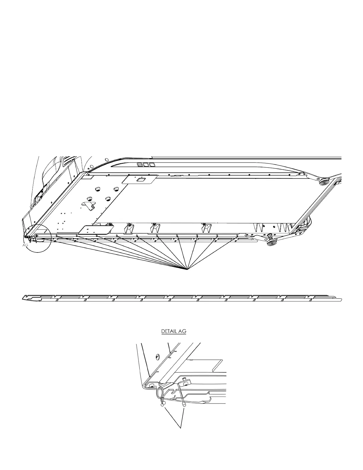
Step 22 Prepare Treadmill (Optional):
a) Power on the treadmill and press the Quick Access key located on the le Contact Heart Rate grip to increase
the incline to six percent. Remove the power cord from the wall receptical, which provides ample working space
for this installation. Place protective padding on the oor and carefully place the treadmill on its le side on the
protective padding. Loosen the 11 notated screws already assembled on the treadmill frame and position the
corresponding 11 slots on the power cord managment hardware between the 11 screws and the treadmill frame.
Note: e TC900 should already be assembled before proceeding with Step 1 (Preparing Treadmill).
Note: Position the wire retainer clips as shown below.
Cord Management Hardware
Pre-assembled treadmill frame screws for cord management hardware
Wire Retainer Clips