11EN
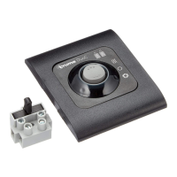
Control panel installation
1. Reserve a place for the control panel (4) in an easily visible
location. Connector cable length 6 m. A 5 m extension cable
is available if necessary (part no. 34300-01).
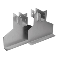
A surface-mounted frame (7) can be used if flush mount-
ing of the control panel is not possible. This is also avail-
able as an accessory (part no. 40000-06400).
2. Drill a hole with diameter of 55 mm. Lead the ten-pole plug
on the control-panel cable (2) through the hole from the back
and connect it to the control panel.
3. Place on the rear blank cover (1) as a strain relief and se-
cure the control panel (4) with 4 screws (3). Then attach the
cover frame (6).
Truma supplies side parts (5) (part no. 34000-66800) to
improve the appearance of the cover frame (6).
4. Protect 12 V lead (9) using provided 1 A fuse (8). (Fuses not
included in industrial bulk pack!)
Red = positive
Blue = negative
If the equipment is connected directly to the battery, the posi-
tive and negative lines must be protected.
If necessary, the voltage supply can be lengthened with an
extension cord of 2 m x 0.75 mm².
When power supply units are being used, make sure that
the output voltage is between 11 V and 15 V.
12 V
8
10
5
6
3
4
7
1
2
55 mm
9
+-
Figure 5
Function check
The operation of the remote indicator must be tested after in-
stallation, as described in the operating instructions.
The operating instructions must be handed over to the vehicle
operator.
 Loading...