18
47000-00082 · 01 · 11/2021
Installation
Truma iNet X Panel / Truma iNet X Pro Panel
EN
Connect the open end of the iNet X connector cable
in the vehicle with unswitched 12V operating volt-
age (steady plus)�
Connect the iNet X connector cable to the control
panel�
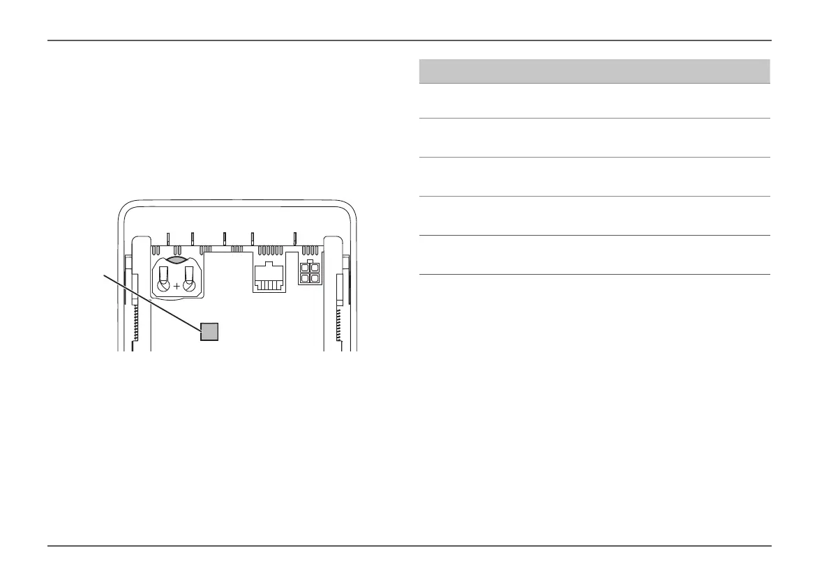
For strain relief, fix all cables with a cable tie to the
lug (Fig� 2-1) on the back of the control panel�
TS1 CAN CI TIN 12 VTS2
1
Fig� 2
Labelling Meaning
CAN
Interface for devices / accessories
(Controller Area Network)
TIN
Interface for Truma devices
( Truma Interconnect Network)
CI
Interface for third-party appliances
(Caravan Industry Bus)
TS1
Temperature sensor 1
(Temperature Sensor 1)
TS2
Temperature sensor
(Temperature Sensor 2)
4.3.1 Connecting temperature sensors
If a room temperature sensor is used, then this must be
plugged into the TS1 connection�
If an outdoor temperature sensor is used, then this
must be plugged into the TS2 connection�
If other temperature sensors need to be connected,
this will be described in the corresponding product
manual� A temperature sensor that is plugged into
the control panel can be used for temperature con-
trol of the Combi (from year of manufacture 2019)�
The room temperature sensor of the Combi can be