47000-00082 · 01 · 11/2021
Installation
Truma iNet X Panel / Truma iNet X Pro Panel
17EN
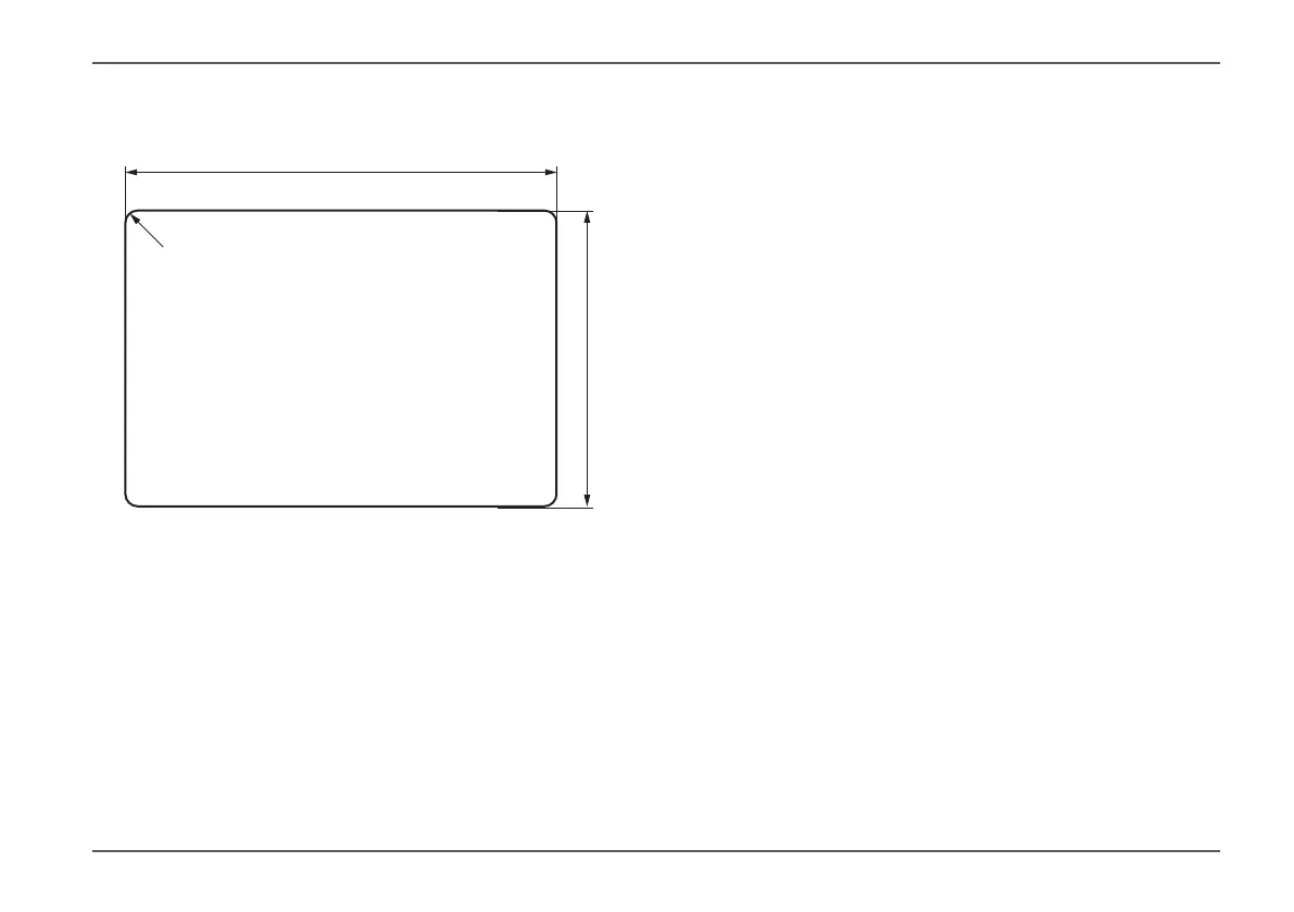
4.2 Making the installation opening
b
c
Fig� 1
a = 108 mm ± 1 mm
b = 84 mm ± 1 mm
c = radius 5 mm
Illustration not to scale�
Mark the installation opening (Fig� 1)�
To do this, transfer the dimensions�
Make the installation opening�
4.3 Electrical connection
The control panel and the devices to be controlled with
this control panel must be connected to the same 12 V
circuit�
Protect the positive cable with a 1 A fuse (near the posi-
tive terminal of the power source)�
Feed all cables to the control panel through the in-
stallation opening from behind and connect them
to the control panel� Lay cables in loops to avoid
tension�
It must be possible to pull the control panel out of the
installation opening by approx� 20 cm� The plug-in con-
nections must not be subjected to any tension� Do not
pull on the cables when they are connected to the con-
trol panel�
Guide the control cable to the devices to be connect-
ed (heating, air conditioning, accessories, etc�) and
connect it to the control panel (TS1, TS2, CAN, CI,
TIN)�
A TIN distributor (part no� 36120-01) can be used to
connect several TIN-capable appliances to the TIN
connection�