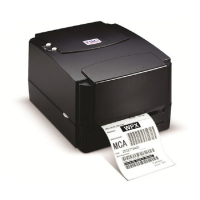
3.12 Cutter Drive Circuit
Fig. 3.12 Cutter Drive Circuit
This is the cutter drive circuit. The RESET signal is 1 when the printer is turned on.
/CT_EN controls the activation of the cutter. The cutter is activated when CUTTER
signal is “low”. The sensor of cutter sends the “Hi-Lo” signal to MCU through CT_SENS
that detects the action of cutter.
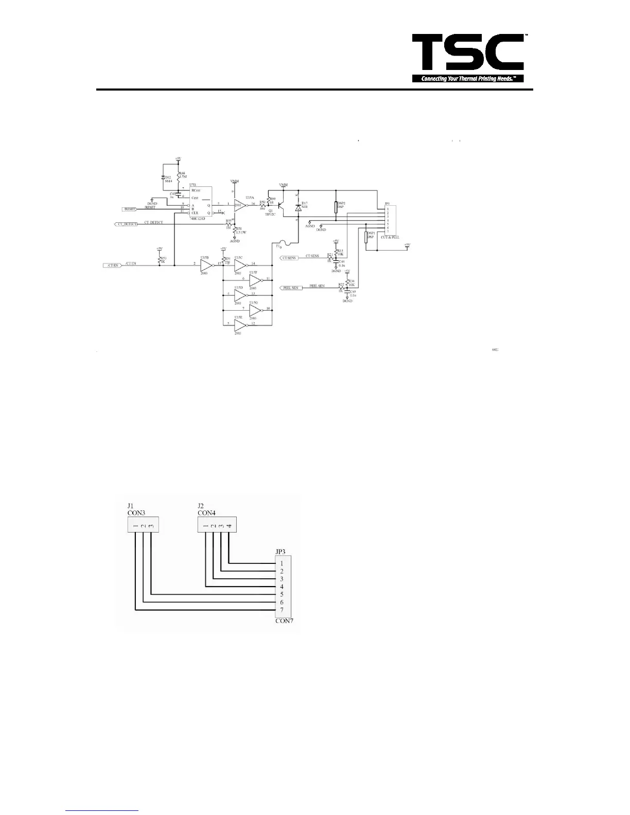
3.13 Cutter & Peel Translate Board
Cutter and peel connector circuit.
JP1 connect to peel module.
JP2 connect to cutter module.
JP3 connect to main board JP3.