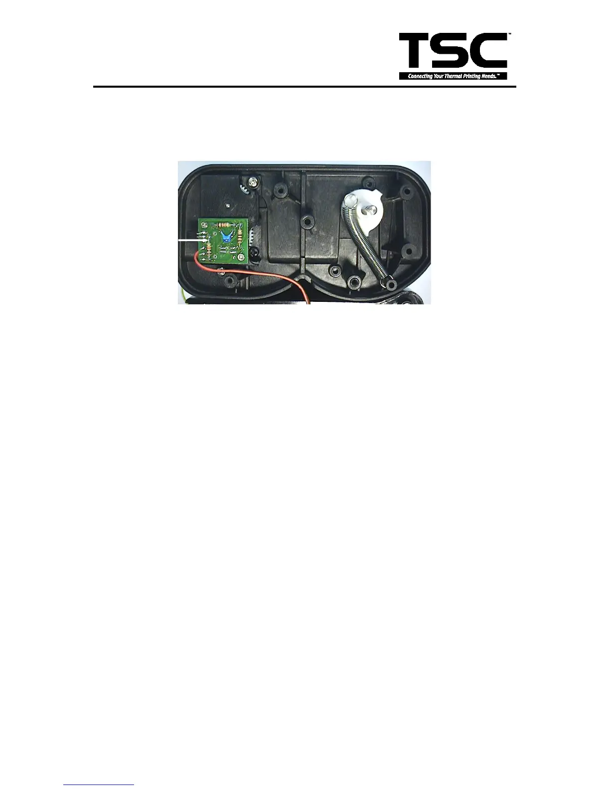
to measure the voltage of Pin2 (+5V). If the voltage changes continuously from 0 to 5
volts DC, the encoder is in condition. Otherwise, please follow the steps below to
replace the encoder PCB
1. Follow directions in Section 4.3 to remove DC motor and DC motor fixture.
Fig. 4.5 DC Motor Encoder
2. Remove the two flat tap screws and cable tie.
3. Replace the Encoder PCB.
4. Reassemble the removed parts in the reverse order of removal.