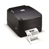
5. Remove the two screws and the metal cover. (Cf. Fig. 3.15)
6. Release the cable tie and remove the peel-off sensor connector. (Cf. Fig. 3.16)
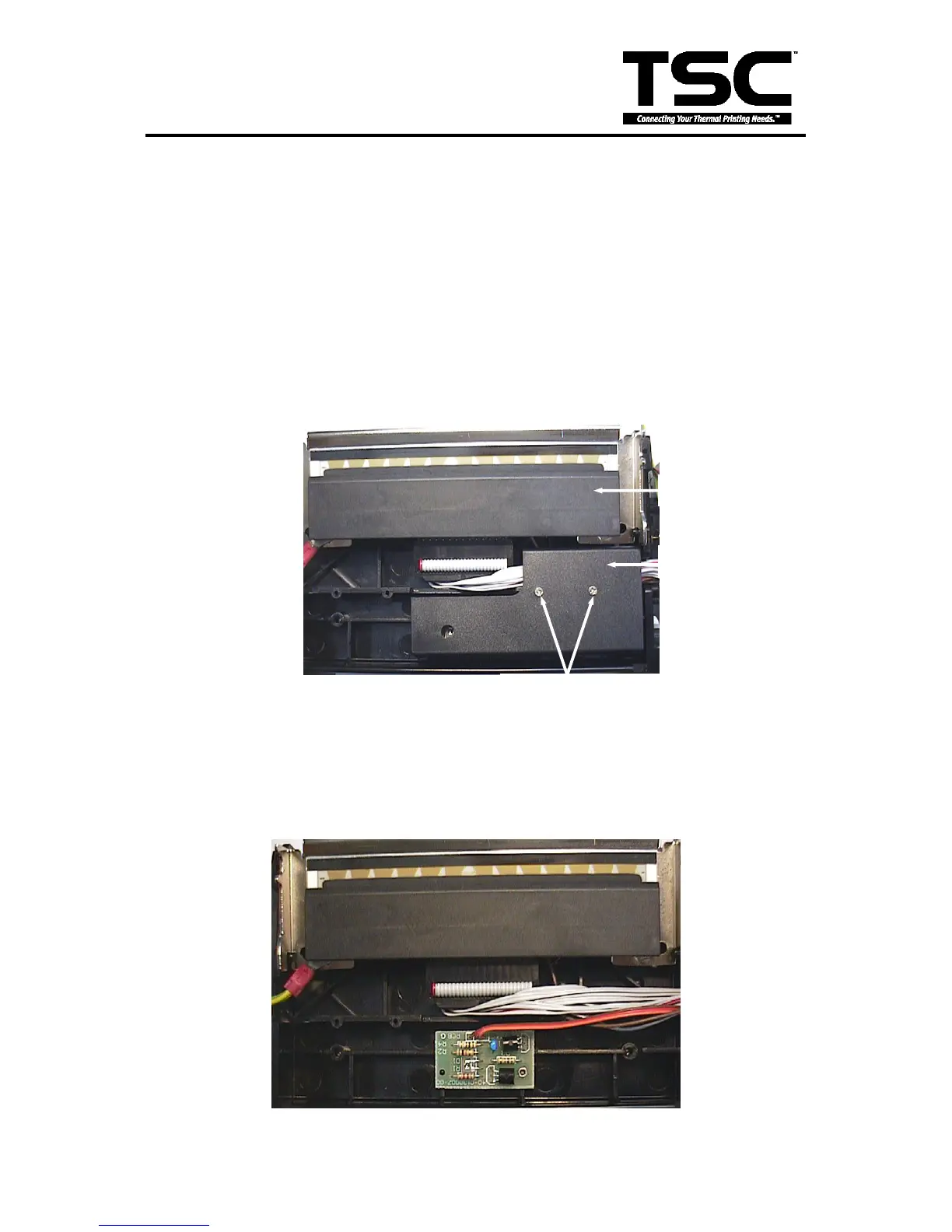
7. Remove the screw on the PCB of peel-off and cutter connector.
8. Remove the screws in the lower left, lower right corners of the main mechanism. (Cf. Fig. 3.17)
9. Remove all four screws of the internal label roll mount. (Cf. Fig. 3.18)
10. Move the mechanism in the label feed direction about 5 mm.
11. Take out the internal label roll mount and remove the connector. (Cf. Fig. 3.19)
12. Remove the screw of ground wire on the mainboard.
13. Remove all the connectors on mainboard. (JP1, JP2, JP3, JP4, JP5, JP6, JP7, JP11, JP7,
JP9, JP12)
14. Take out the mechanism.
15. Remove the screws, springs and spring bushing on both sides of the mechanism.
Fig. 4.11 Ribbon Sensor Cover