PCM30U, PCM30U-OCH – User's, Operating and Maintenance Manual
E.1.6 Schematics
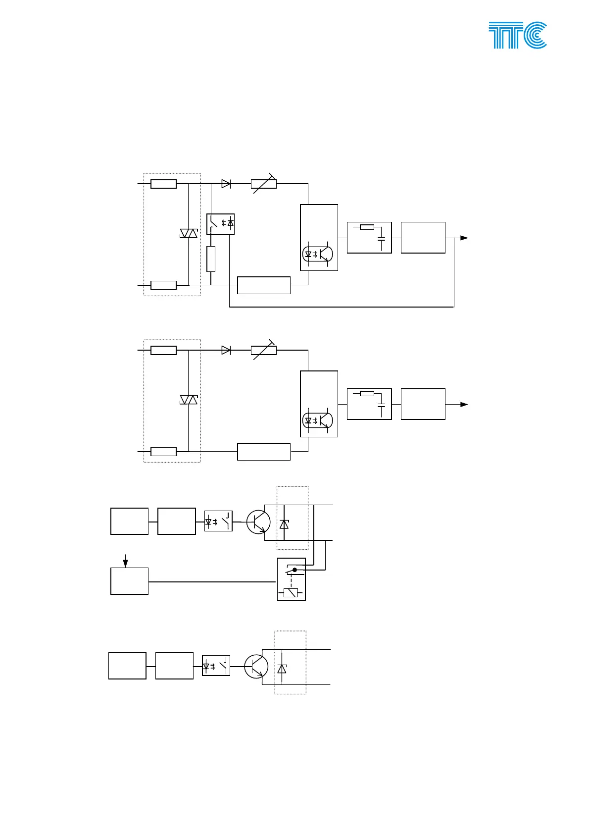
E.1.6.1 Inputs and outputs
Fig 2 Schematic of inputs and outputs
Current limiter with
optorelay
Optocoupler
and
supporting
circuit
RC filter to
remove glitches
Logic level
converter
dditional load
switched off when
U in
ut > U threshold
Resistor network for
nominal voltage selection
configurable by jumpers
4 kV
and 300 V
protection
+ In
ut
- In
ut
Input 1 to 4
I to Xilinx
Current limiter with
optorelay
Optocoupler
and
supporting
circuit
RC filter to
remove glitches
Logic level
converter
Resistor network for
nominal voltage selection
configurable by jumpers
4 kV
and 300 V
protection
+ In
ut
- In
ut
Input 5 to 10
I to Xilinx
Outputs 1 to 4
Switch ON
accelerate
circuit
Optorelay
Logic level
converter
Level
converter
logic / -Ubat
300 V
Protection
-Ubat
+Out
ut
-Out
ut
Outputs 5 to 10
Switch ON
accelerate
circuit
Optorelay
Logic level
converter
300 V
Protection
+Out
ut
-Out
ut
Power Channel Modules E-13 446S037.914.14N00