PCM30U, PCM30U-OCH – User's, Operating and Maintenance Manual
E.2.5 Configuration jumpers
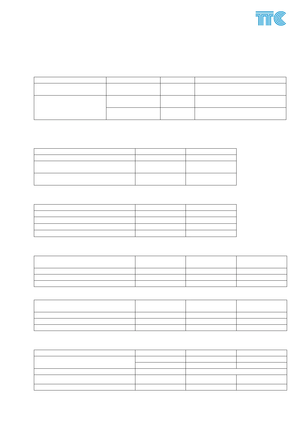
E.2.5.1 Mode of the unit
XJ1 - 7 XJ1 - 7
Comparison protection
(setting A)
not installed not installed !!!
(reserved for manufacturing test)
transmitting direction
50 HZ-IN)
installed not installed
Generator synchronication
(setting B)
receiving direction
50 HZ-OUT)
installed
E.2.5.2 Channel feedback control
Feedback control may only be used in B mode – generator synchronisation
Channel feedback control 1
st
channel 2
nd
channel
XJ100 – 1,2 XJ200 – 1,2
Output connected to input for feedback
tranmsission for checking
Jumpers installed Jumpers installed
Output disconnected from input – check
not used
--- ---
E.2.5.3 Input resistance
R
IN
(50Hz) 1
st
channel 2
nd
channel
XJ101 XJ102
> 50 kΩ
- -
5 kΩ
1-2 1-2
2 kΩ
2-3 2-3
E.2.5.4 Maximum input voltage
Max. input U
IN
(50Hz) 1st channel 2nd channel Information for
Doris
XJ102 XJ202 XJ8-2
110 Vrms 1-2 1-2 not installed
70 Vrms 2-3 2-3 installed
E.2.5.5 Maximum output voltage
Max. input U
OUT
(50Hz) 1st channel 2nd channel Information for
Doris
XJ103 XJ203 XJ8-1
100 Vrms 1-2, 3-4 1-2, 3-4 not installed
50 Vrms 1-3 1-3 installed
E.2.5.6 Digital delay
Digital delay XJ1 not installed installed
5 0 ms 8 ms
1
st
channel
6 0 ms 16 ms
+ms1 +0 to +7.5 ms on panel, by 0.5 ms
XJ1 not installed installed
1
st
channel
3 0 ms 8 ms
Power Channel Modules E-35 446S037.914.14N00