PCM30U, PCM30U-OCH – User's, Operating and Maintenance Manual
E.1.3 Elementary scheme
Front panel
Reset
LM
M
LED
in / out
submodule
Test
PW,ER,TST
SK
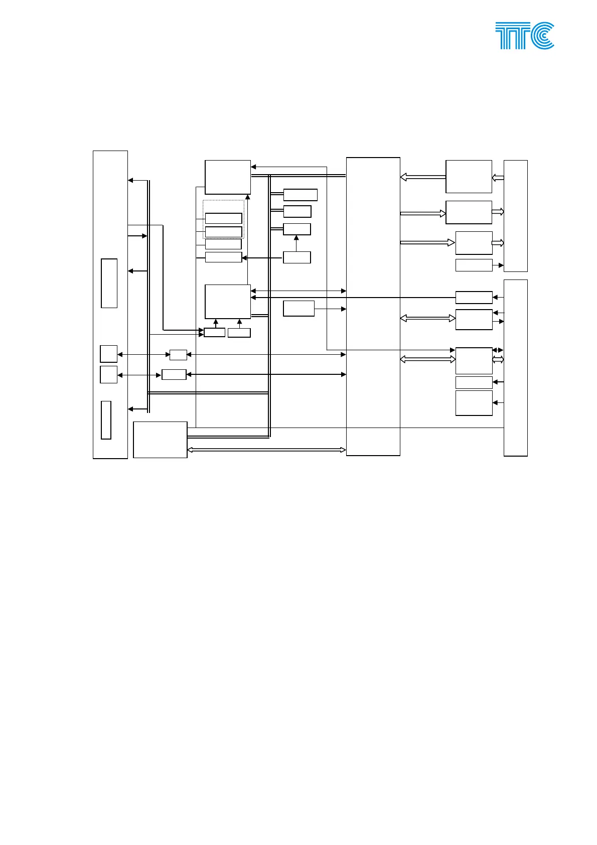
Fig 1 Block diagram of the PBS module
Heart of the unit is PLD Xilinx, which makes all security, time filtering, prolonging, shortening. Microcomputer
is responsible for configuration, communication with management system, log of commands and alarms.
Configuration is stored in two seeprom, can be loaded also from seeprom located at backplane in 6OCH8,
6OCH4. Unit checks 5 V, 3 V and –Ubk used for feeding relays. Switches are used for basic configuration.
INPUT 1-4
INPUT 5-10
QUIT
PW connecte
XC202
OUTPUT 1-4
OUTPUT 5-10
ERR1
ERR2
-Ub / -24 V
unit to backplane connecte
XC8
-Ub
internal data
3.3V / 5V
converter
5V
soft
start
5 V
3 V
KJ position
ext. sync.
V.11
Submodule
interface
PLD
Xilinx
V.11
RS232
Microcomputer
FLASH
BSRAM
seeprom1
seeprom2
real time
thermometer
battery
CPLD
RST
WD 5V
WD 3V
LEDS
Buttons
LEDS
LEDS
LM
1
E2
2
VCO
67 MHz
MROM-cfg
cf
I
C bus
cfg from
backplane
ddress / Data
buss
Power Channel Modules E-5 446S037.914.14N00