PCM30U, PCM30U-OCH – User's, Operating and Maintenance Manual
E.1.10 PBS shorters and mechanical configuration
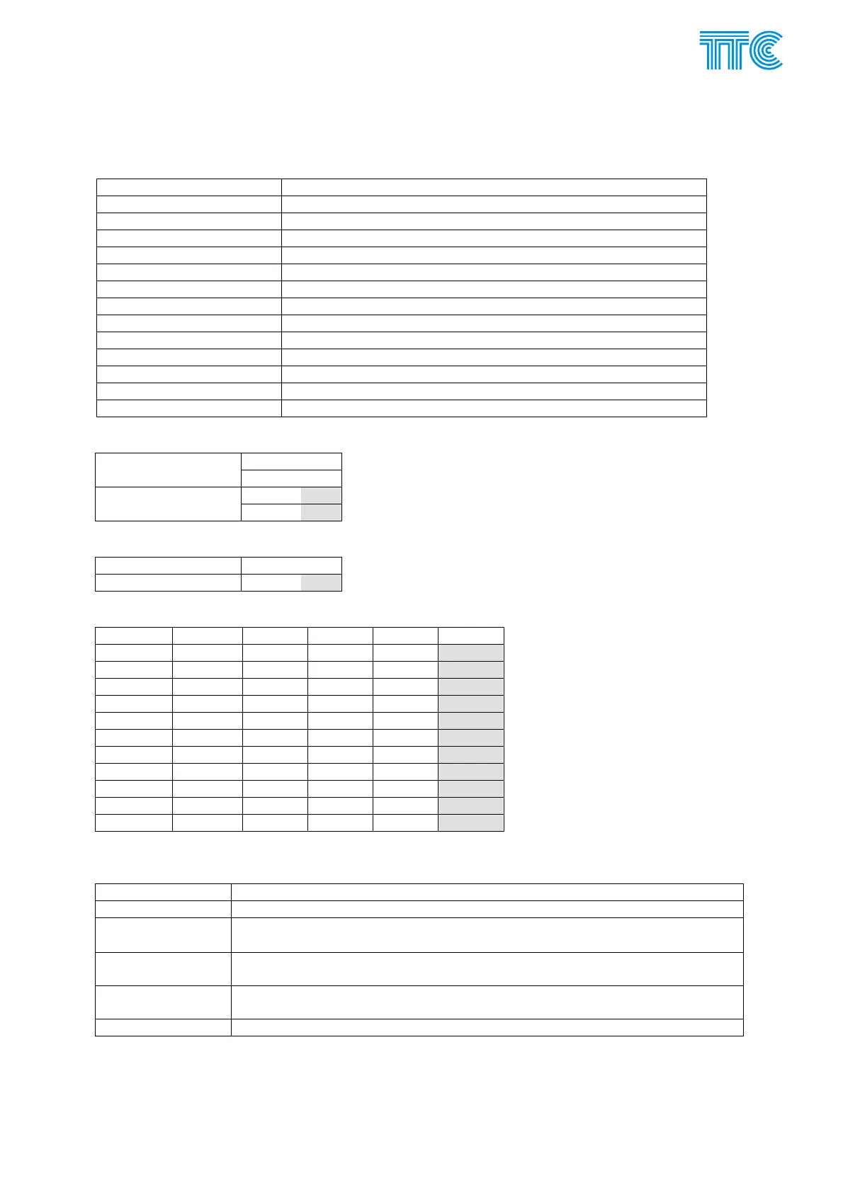
Jumper Meaning
XC1 Boundary scan connector
XC2, XC3 Line interface submodule connector
XC5 Display connector (optional)
XC6 LM local interface connector
XC7 M interface connector (management channel)
XC201 Connector for connecting of commands and alarm contacts
XJ2, XJ5 GND
XJ3 +5V
XJ4 +3,3V
XJ6 AUX1 – factory test point
XJ7 AUX2 – factory test point
XJ8 AUX4 – factory test point
DS1 Program memory
E.1.10.1 Setting the functioning of ERR1 alarm opto-relay
XJ800 2-3
alarm = cloth
XJ801 1-2
XJ800 1-2 alarm = open
XJ801
2-3
E.1.10.2 Setting the functioning of ERR2 alarm elektromechanical relay
alarm = cloth XJ802 1-2
alarm = open XJ802 2-3
E.1.10.3 Setting command nominal input voltage
command jumper 24 V 48 V 110 V 220 V
1 XJ200 2-3 1-2, 3-4 1-2 —
2 XJ220 2-3 1-2, 3-4 1-2 —
3 XJ240 2-3 1-2, 3-4 1-2 —
4 XJ260 2-3 1-2, 3-4 1-2 —
5 XJ280 2-3 1-2, 3-4 1-2 —
6 XJ300 2-3 1-2, 3-4 1-2 —
7 XJ320 2-3 1-2, 3-4 1-2 —
8 XJ340 2-3 1-2, 3-4 1-2 —
9 XJ360 2-3 1-2, 3-4 1-2 —
10 XJ380 2-3 1-2, 3-4 1-2 —
Qvit XJ400 2-3 1-2, 3-4 1-2 —
Gray marked fields indicates factory default settings.
E.1.10.4 Configuration switches
SA3(1..4) Unit identification for command group transmitted to A direction
SA4(1..4) Unit identification for command group transmitted to B direction
SA7(1..4)-SA6(1..2)
M management address in binary form (2
0
÷2
5
)
M = SA7(1) x 1 + SA7(2) x 2 SA7(3) x 4 + SA7(4) x 8 SA6(1) x 16 + SA6(2) x 32
SA6(3) Lock configuration of PBS functions to prevent inappropriate actions from the
management system
SA6(4) Lock configuration of PWA functions to prevent inappropriate actions from the
management system
SA5(1..4) For future use. Not assembled after January 2009
Power Channel Modules E-23 446S037.914.14N00