Tuff Torq K92 Hydrostatic Transaxle
Charge Pump Disassembly and Assembly (continued)
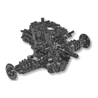
A - Cap Screw (2 used), M10 x 65
B - Plug
C - O-ring
D - Pump Body
E - Pressure Valve
F - Spring
G - O-ring
H - Plug
I - Shims
J - Pin
K - O-ring
L - O-ring
M - O-ring
N - Outer Rotor
O - Key
P - Inner Rotor
Q - O-ring
R - Plug
S - Reducing Valve
T - Spring
U - Reducing Plug
V - O-ring
W - Bushing
X - Seal
Y - Cap Screw, M10 x 105
6. Check small orifice in reducing valve (S) spool
for obstruction.
7. Replace parts if necessary.
8. Remove plug (H) to remove charge pressure relief
valve parts (E, F, G, and I). (Fig. 3)
9. Inspect parts for scoring, wear or damage.
10. Replace parts if necessary.
11. Inspect seal (X) and bushing (W) for wear or damage.
12. If bushing is removed, apply clean hydraulic oil to
bushing and use a disk driver to install bushing to
bot-tom of bore.
13. If seal is replaced, apply clean hydraulic oil to new
seal. Install seal with open side into pump body.
Push seal to bottom of bore.
14. Apply clean hydraulic oil to all machined surfaces
before assembly.
NOTE: Installation is done in the reverse order of removal.
NOTE: Charge pressure control valve and pressure
reducing valve can be removed when the charge pump
is in the machine. To inspect valve seats and bores,
the pump must be removed.
1. Disassemble all parts of charge pump (D). (Fig. 3)
2. Inspect O-rings (C, K, L, M, and Q) for cuts or
damage. Replace as necessary. (Fig. 3)
NOTE: Pump gerotor (N and P), seal (X), body (D), and
pressure reducing valve (S) parts must be replaced as a set.
3. Inspect gerotor charge pump parts (N - P). Replace
parts if worn, chipped, scored or damaged.
4. Remove plug (U) to remove pressure reducing
valve parts (V, S, and T). (Fig. 3)
5. Inspect parts for scoring, wear or damage.
3