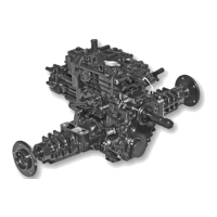
Tuff Torq K92 Hydrostatic Transaxle
7. Inspect final gear (F) for worn or damaged teeth.
(Fig. 39)
8. Inspect ball bearings (A and D) for smooth rotation.
(Fig. 39)
NOTE: Final pinion shaft (C) and final gear (F) must be
re-placed as a set. Bevel input gear (B) and bevel input
pinion (not shown) must be replaced as a set.
9. Check bevel input gear (B) and final pinion shaft (C) for
worn or damaged condition. Replace parts as necessary.
(Fig. 39)
10. Install final gear on differential holder and carrier
with the deeper offset of gear center away from the
holder. Tighten eight differential cap screws (M) to
88 N•m (65 lbft).
11. Install differential lock collar (N) and left and right
bear-ings (O). Push bearing tight against shoulder of
differen-tial holder. (Fig. 39)
12. Install remaining components.
NOTE: Use medium strength thread lock and sealer.
Differential (4WD) Disassembly and Assembly
Fig. 40, Differential (4WD) Disassembly
A - Ball Bearing I - Washer (2 used)
B - Bevel Input Gear J - Pinion Gear (2 used)
C - Final Pinion Shaft K - Differential Pinion Shaft
D - Ball Bearing L - Left-Notched Differential Gear
E - Ball Bearing (2 used) M - Final Gear
F - Differential Holder, Right N - Differential Holder, Left
G - Liner (2 used) O - Washers (8 used)
H - Right Differential Gear P - Cap Screws (8 used)
Q - Differential Lock Collar
21