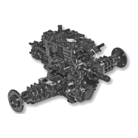
Tuff Torq K92 Hydrostatic Transaxle
Brakes Removal and Installation
A - Snap Ring
B - Brake Actuator Plate
C - Friction Plate
D - Steel Plate
E - Steel Ball
F - Clevis Pin
G - Washer
H - Spring Lock Pin
I - O-ring
J - Interlock Plate
K - Cotter Pin
L - Washer
M - Rod
N - Adjustment Nut
O - Nut
P - Rod
Fig. 78, Brake Disassembly
Q - Cam Lever
R - Brake Cover
S - Cap Screw
1. Inspect components on brake cover (R). Replace as
nec-essary. Apply petroleum jelly to O-ring. (Fig. 78)
2. Inspect plates for wear or spline damage. If groove pat-
tern in friction plates is no longer visible, replace plates.
3. Apply petroleum jelly to balls (E) and install balls
in cover.
4. Install steel plates (D) and friction plates (C)
alternately beginning with a steel plate.
5. Apply a bead of silicon sealant to brake cover
mating surface of transaxle case.
6. Install brake actuator plate (B) and brake cover assembly
(R).
Brake Cover Cap Screw Torque Specifications:
Used Transaxle Case . . . . . . . . . . . . . . 25 N•m (18 lb-ft)
New Transaxle Case . . . . . . . . . . . . . . . 30 N•m (22 lb-ft)
43