9. Position solenoid coil wire leads (P) to the right
and approximately 45° above horizontal.
IMPORTANT: Avoid damage! When tightening
plastic nut be sure to tighten nut to exact
specifications. Nut has a very low torque. Any
overtightening will damage the armature coil.
10. Tighten plastic nut (O) to 4.9 N•m (43 lb-in.). (Fig. 11)
Fig. 11, PTO Electrical Solenoid
PTO Relief Valve Removal and Installation
Fig. 12, Relief Valve Plug
1. Remove relief valve plug. (Fig. 12)
2. Install relief valve plug (A) and tighten to 25 N•m
(19 lbft).
PTO Relief Valve Disassembly, Inspection
and Assembly
Fig. 13, Relief Valve Assembly
1. Disassemble PTO relief valve. (Fig. 13)
2. Check relief valve plunger and bore for scoring,
nicks or burrs. Replace if necessary.
3. Install spring (B), gasket (C), relief valve plunger (A),
and plug (D) in PTO cover. (Fig. 13)
PTO Brake Removal and Installation
NOTE: Approximate capacity of hydrostatic power train
is 7.5L (7.9 qt) for 2WD and 7.8L (8.2 qt) for 4WD and
9.0L (9.5 qt) for 4WD w/rear PTO.
CAUTION: Avoid Injury! Allow transaxle to cool before
drain-ing fluid. Hot fluid can cause serious burns.
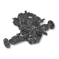
Fig. 14, Transaxle/Rear PTO Cover
6