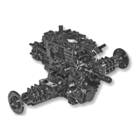
Tuff Torq K92 Hydrostatic Transaxle
L - O-ring
M - PTO Brake Shoe
N - PTO Clutch Assembly
1. Carefully pull piston assembly from case using a
pliers. Do not damage pin. (Fig. 17)
2. Remove PTO clutch assembly (N) and brake
shoe (M) together.
NOTE: PTO brake pin, piston, springs, and O-rings,
etc., (parts C thru I), must be replaced as a set.
3. Check pin and piston for burrs, scoring or wear.
4. Replace brake shoe if grooves in shoe contact
surface are not visible.
5. Inspect O-rings for cuts or damage.
6. Inspect springs for cracks or damage.
7. Apply petroleum jelly to O-rings and seal on end of
PTO clutch shaft.
8. Install piston assembly and clutch assembly.
9. Clean mating surface of side cover and transaxle
case. Be sure threaded holes are clean.
10. Apply a bead of silicon sealant to cover mating of
sur-face.
IMPORTANT: Avoid damage! Be sure side cover is
aligned with transaxle case and installed within 3 mm
(1/8 in.) of case before tightening cap screws. Major
damage can occur to cover and/or case if cover is not
installed properly before tightening cap screws.
Transaxle Cover Cap Screw Torque Specifications:
• Used Transaxle Case . . . . . . . . . . . . . . 25 N•m (18 lb-ft)
• New Transaxle Case . . . . . . . . . . . . . . . 30 N•m (22 lb-ft)
NOTE: Remove necessary rear PTO components
before rear transaxle cover removal. (See “Rear PTO
Removal and Instal-lation” on page 14.)
2. Remove optional rear PTO (A), if installed. (See “Rear
PTO Removal and Installation” on page 14.) (Fig. 18)
3. Remove rear transaxle cover (C). (Fig. 18)
Fig. 18, Transaxle Cover
4. Remove PTO clutch assembly (A). (Fig. 19)
5. Remove PTO idler gear assembly (N). (Fig. 19)
6. Remove PTO gear (K). (Fig. 19)
7. Left axle must be removed to remove PTO output
shaft assembly (L), (See “Rear Axle Assembly
Removal and Installation” on page 41.)
PTO Drive Train (Mid-PTO) Removal and
Installation
NOTE: Approximate capacity of hydrostatic power train
is 7.5L (7.9 qt) for 2WD and 7.8L (8.2 qt) for 4WD and
9.0L (9.5 qt) for 4WD w/rear PTO.
Removing:
CAUTION: Avoid Injury! Allow transaxle to cool before
drain-ing fluid. Hot fluid can cause serious burns.
1. Remove plug (B) to drain oil from transaxle. (Fig. 18)
9