Hydrostatic Pump Inspection (continued)
A - Washers
B - Piston Spring (7 used)
C - Snap Ring
D - Cylinder Block
E - Washer
F - Spring
G - Piston (7 used)
H - Thick Thrust Plate
I - Thrust Bearing
J - Thin Thrust Plate
IMPORTANT: Avoid damage! Keep pistons matched
with bore of cylinder block. Do not interchange motor
pistons and valve plate with pump pistons and valve
plate. Pistons and cylinder blocks are a matched set.
1. Spring is compressed. Apply an external force to
com-press spring farther before removing snap
ring. Then slowly remove external force.
2. Remove parts from transaxle as necessary.
NOTE: Pump rotating components must be replaced
as a set. Thin thrust plate must be replaced as a set
with the pump swash plate and bushing.
3. Check cylinder block for grooves, scoring,
discoloration or pitting.
NOTE: Scoring is fine scratches or grooves cut into the highly
machined surface. When the scratches can be detected by feel
using a lead pencil or fingernail, the part must be replaced.
4. Check for free movement of pistons in cylinder bores.
5. Check pistons for flat areas, scoring or
discoloration. Thrust bearing must rotate freely.
For inspection of pump valve plate, refer to “Center
Valve Block Disassembly and Assembly:” on page 33.
Transaxle Disassembly
1. Remove control arm damper. (See “Control Arm
and Damper Removal and Installation” on page 1.)
2. Remove hydrostatic transmission and pump. (See “Hy-
drostatic Transmission 2WD and 4WD” on page 35.)
3. Remove axle housings. (See “Rear Axle Assembly Re-
moval and Installation” on page 41, and See “Rear Axle
Assembly - Disassembly and Assembly” on page 42.)
4. Remove brakes. (See “Brakes Removal and
Installation” page 43.)
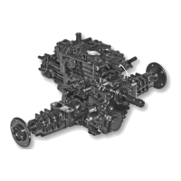
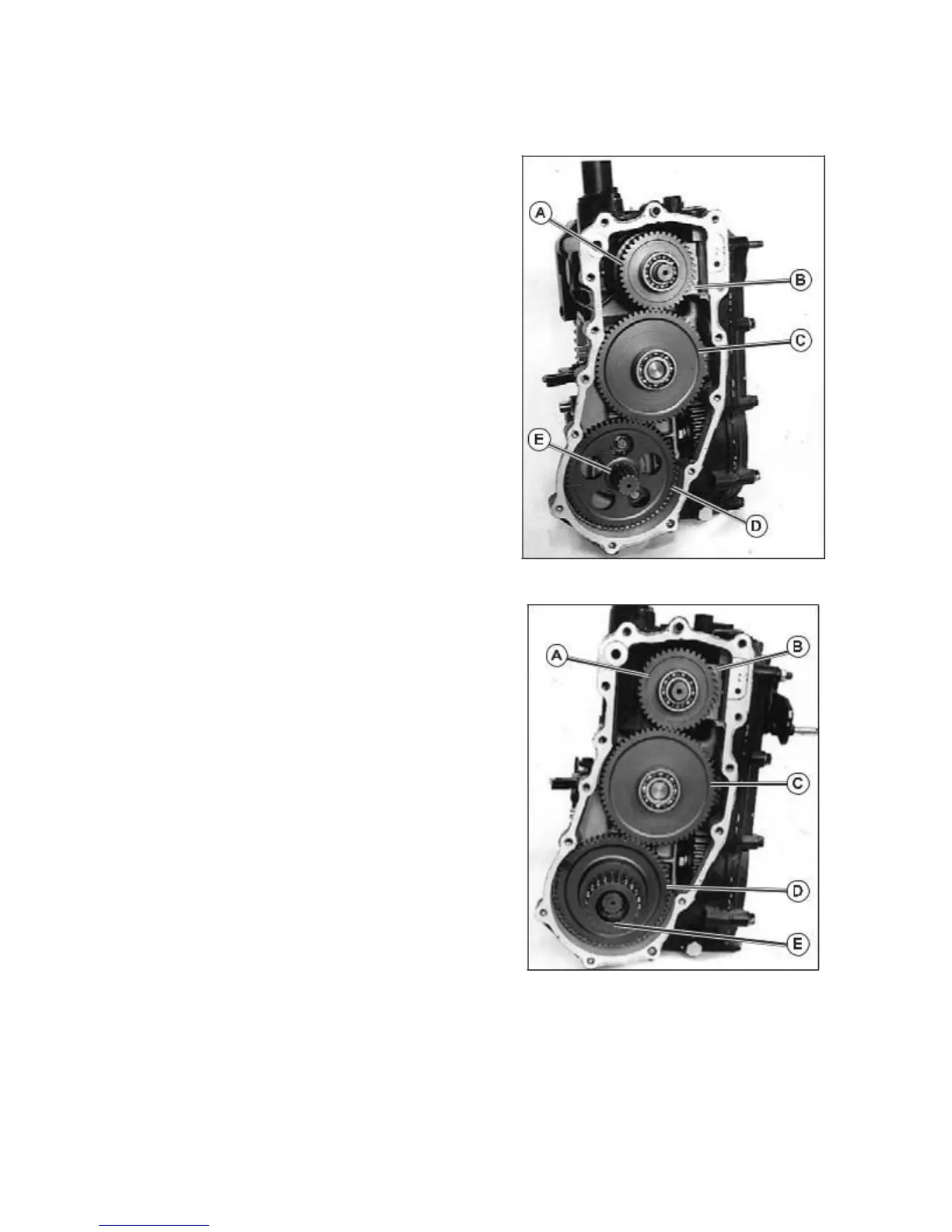
5. Remove PTO idler shaft assembly (C), snap ring
(E), PTO gear (D) (or rear drive gear set).
Fig. 61, Without Rear PTO Option
Fig. 62, With Rear PTO Option
6. Remove PTO brake shoe (B) and clutch (A). (See
“PTO Brake Removal and Installation” on page 6.)
7. Remove large snap ring (H) and input shaft assembly.
8. Remove large snap ring (L), small snap rings (G and K)
washers (M and J), and ball bearing (I) from input shaft
(F). (Fig. 63)
36