4WD Output Disassembly and Assembly
1. Drain transaxle.
CAUTION: Avoid Injury! Allow transaxle to cool before
drain-ing fluid. Hot fluid can cause serious burns.
2. Remove bolt/washer (I, J) and drain the 4WD gear box.
3. Remove (11) bolts (H), bolt (AK), and bolt (AH) from
4WD cover.
4. Remove 4WD cover (A).
NOTE: To avoid damage, during separation, to the cover
and/or the gear box, use the pry points shown in fig. 44.
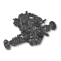
Fig. 44, 4WD Cover Removal
5. Remove the drive gear (AC) from motor shaft.
6. Remove the first press bearing (E), gear (Y), washer (Z),
and gear (AA) from 4WD reduction shaft (X). Remove
4WD reduction shaft (X), and the second press bearing
(E) from the 4WD gear box as a single item. (Fig. 46)
7. Remove press bearing (E) from 4WD reduction shaft (X).
NOTE: When reinstalling, take care to place gears in their
original order; with the thicker gear in front (with raised sur-
face towards the bearing) and the thinner gear behind.
Fig. 46, 4WD Cover Removal
8. Remove snap rings (V) and (AM); then, gear (R) from shaft
(S). Remove snap ring (AN) and remove (S, T, U, V, W,
and AO) as a single item from the 4WD gear case.
9. Remove press bearing (AO), collar (W), snap ring (V),
press bearing (U), and collar (T) from shaft (S). (Fig. 47)
NOTE: Flat end of shift collar goes toward bearing.
10. Clean bearings in a suitable solvent. Dry with
com-pressed air.
IMPORTANT: Avoid damage! DO NOT spin bearing
using compressed air. Damage to bearing balls, cage,
and races could result.
11. Inspect bearings for discolored, burned, balls and/or
races. Check balls and races for spalling or cracking.
Roll bearing by hand to check for rough turning or
excessive looseness or play between balls and
races. Replace bear-ings as required.
Fig. 45, 4WD Cover Removal
NOTE: Snap ring (AD) on motor shaft does not need
to be removed for the 4WD gear case removal. Unless
replacement is necessary. (Fig. 52).
Fig. 47, 4WD Cover Removal
24