Directional Control Valves
Removal and Installation:
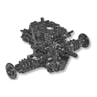
Fig. 4, Control Valves
1. Remove directional control valves (A). (Fig. 4)
NOTE: Installation is done in the reverse order of removal.
• Tighten directional control valves to 35 N•m (26 lb-ft).
Disassembly, Inspection and Assembly:
Fig. 5, Control Valve Disassembly
A - Reverse Control Valve (with orifice)
B - Orifice
C - Forward Control Valve
D - O-ring
E - Backup Ring
F - O-ring
1. Disassemble parts from directional control valves.
2. Inspect O-rings and backup rings for damage.
3. Plunger pin must move freely.
4. Internal valve must move freely when valve is shaken.
5. Make sure orifice and all passages are free of
any obstruction.
6. Assemble parts.
a land between the two sets of valve passageways.
Fig. 6, Control Valve Location
PTO Solenoid Valve
Removal and Installation:
IMPORTANT: Avoid damage! Do not bend, twist or
damage solenoid armature. Do not damage machined
sur-faces or sharp edges of spool or sleeve. PTO will
not function or will function erratically if spool, sleeve or
armature is dam-aged.
Fig. 7, Charge Pump Rotor
4