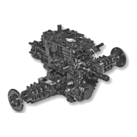
Center Valve Block Disassembly and Assembly (continued)
U - Center Valve Block
V - Needle Bearing (2 used)
W- Locating Pin (2 used)
X - Pump Valve Plate
Y - Anti-Cavitation Valve Body
Z - Backup Ring
AA- O-ring
AB- Ball
AC- Ball Holder
AD- Spring
AE- Retainer
AF- Motor Valve Plate
NOTE: Remove motor assembly if necessary to
inspect nee-dle bearing. (See “Hydrostatic
Transmission Motor Removal:” on page 28.)
1. Remove and inspect directional check valves.
IMPORTANT: Avoid damage! The reverse check valve
must be installed in the left port. The check valve can
be identified by a small orifice drilled into a land
between the two sets of valve passageways.
2. Replace locator pins if missing or damaged.
3. Inspect needle bearings for wear or damage. If
bearings are replaced, install new bearings with the
stamped end away from center valve block.
4. Push bearings into bore until end of bearing is
approxi-mately 3 mm (7/64 in.) above the surface of
the valve block.
5. Inspect anti-cavitation valve assemblies.
NOTE: Screens may be located in bores of transaxle case.
6. Check suction screens for blockage.
7. Carefully pull anti-cavitation valve body from
center valve block so as not to lose parts.
8. Replace parts as necessary.
9. Apply oil to O-rings and push assembly to bottom
of bore.
10. Inspect center valve block where charge pump
contacts block for scoring.
11. Replace center valve block if necessary.
NOTE: Scoring is fine scratches or grooves cut into the highly
machined surface. When the scratches can be detected by feel
using a lead pencil or fingernail, the part must be replaced.
12. Inspect valve plate for grooves, scoring, discoloration
or pitting.
IMPORTANT: Avoid damage! Pump and motor valve
plates are not interchangeable. The pump valve plate
has two lead-ing grooves into two of the slotted ports.
The motor valve plate has no leading grooves.
13. Put pump valve plate on center valve block. Make
sure bronze surface is away from valve block and
notch in valve plate fits on locating pin of valve block.
NOTE: Use petroleum jelly to hold valve plate in position.
14. Remove plug to inspect charge pressure relief
valve parts.
15. Check plunger for nicks, wear or damage.
16. Inspect plunger seat in center valve block. Remove
any obstructions and replace center valve block if
seat is worn or damaged.
Hydrostatic Transmission Motor Installation
NOTE: Replace retaining ring (D) if ring is distorted
during removal.
Fig. 58, Hydrostatic (2WD) Motor
1. Secure motor housing assembly (A) and gasket (F)
to center valve block (B) with (2) lower capscrews
(G). In-stall ball bearing (C) and bevel input pinion
(E) — secure with retaining ring (D).
34