Rear PTO Removal and Installation (continued)
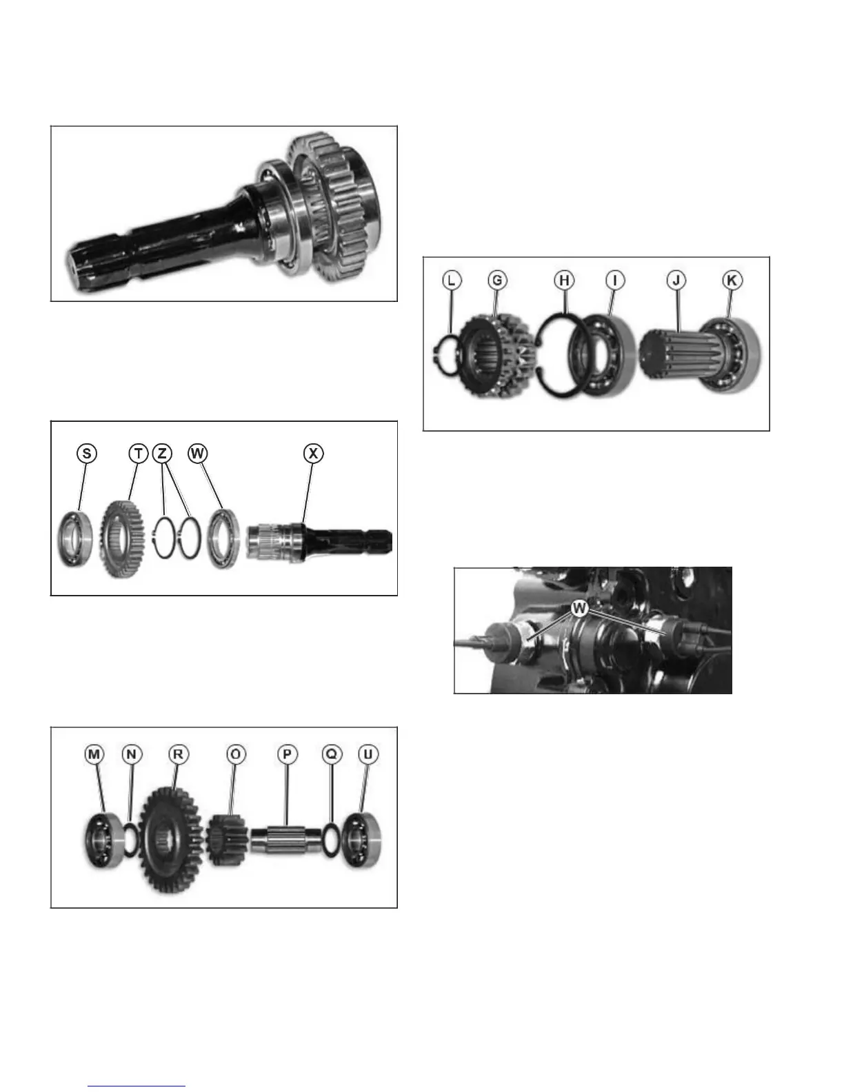
Fig. 32, Rear PTO Shaft Assembly
11. Remove press bearing (S) from the PTO shaft (X); then,
remove PTO gear (T), snap rings (Z), and press bearing
(W) from PTO shaft. Inspect all components for
wear or damage, replace as necessary. (Fig. 33)
Fig. 33, Rear PTO Shaft Disassembly
12. Remove press bearing (M) from idler shaft (P). Remove
washer (N), PTO input gear (R), and idler pinion gear (O).
Remove press bearing (U) and remove washer (Q) from
idler shaft (P). Inspect all components for wear or dam-age,
replace as necessary. (Fig. 34)
Fig. 34, Rear PTO Pinion/Input Gear Disassembly
NOTE: If rear PTO input gear (R), see fig. 34, replacement is
necessary, the shift collar (F), see fig. 36, and rear PTO idler
gear (G), see fig. 35, must be replaced also. The three gears are
available as a set. Rear PTO gear (T), see fig. 33, and rear PTO
idler pinion (O), see fig. 34, must be replaced as a set.
13. Remove snap ring (L), idler gear (G), snap ring (H),
press bearing (I), and press bearing (K) from shaft
(J). Inspect all components for wear or damage,
replace as neces-sary. (Fig. 35)
NOTE: Recall writing/numbers on all outer bearing
races, and install bearings in reverse order as removal.
Fig. 35, Rear PTO Idler Gear Disassembly
14. If necessary, remove ball switch (W) and O-ring.
(Fig. 36)
• If removed, install O-rings and ball switches (W). DO
NOT overtighten. Tighten to 34 N•m (25 lb-ft).
Fig. 36, Ball Switches
15. Inspect all parts and replace as necessary.
Assembly is reverse order of disassembly.
16