Rear PTO Removal and Installation (continued)
Installing:
NOTE: Installation is done in the reverse order of
diassembly. Additional information can be found by
refering to the “Rear PTO Removal and Installation”
removal section, starting on page 14.
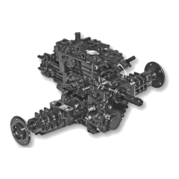
1. Clean mating surfaces of cover (AD) and gear case
(C). Be sure threaded holes are clean. (Fig. 37)
2. If removed, install gear sets in the reverse order of
their disassembly. (Fig. 37)
3. Apply a bead of silicon sealant to any mating surfaces
to be assembled.
IMPORTANT: Avoid damage! Carefully lower cover assem-
bly onto case, making sure bearings fit into bores and gears
mesh properly. Be sure cover is installed within 3 mm (1/8
in.) of case before tightening all cap screws to 25 N•m (18 lb-
ft). Major damage can occur to cover and/or case if not
properly aligned before tightening cap screws.
4. Install PTO assembly on the two alignment
bushings, and tighten tenF), and three M8 x 50 (E)
cap screws to specification below.
5. Install transaxle drain plug. Refill transaxle with
approxi-mately 9.0L (9.5 qt) using ATF Type F to
crosshatched area of dipstick.
Specifications:
• M8 Bolts. . . . . . . . . . . . . . . . . . . . . . . . . 24 N•m (18 lb-ft)
• M12 Bolts. . . . . . . . . . . . . . . . . . . . . . . . 54 N•m (40 lb-ft)
18