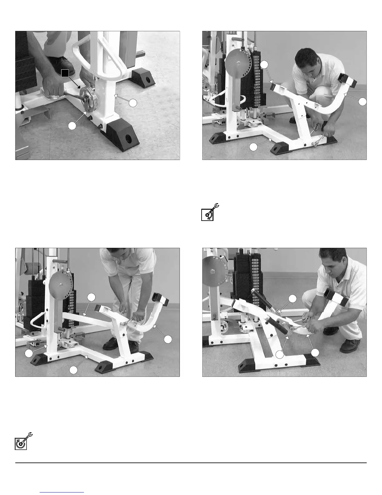
FIG. 53 Next, attach one Pulley 4 1/2 Rd. (#67-Labeled C1) and one
Cable Retainer Bracket (#8) to the Leg Extension Front Frame (#27)
using one Hex Head Cap Screw 3/8-16 X 4 1/4 (#104), one Flat
Washer SAE 3/8” (#93), and one Nylon Insert Lock Nut 3/8-16 (#119).
FIG. 55 Next, attach the Leg Extension Arm Support (#23) to the
Leg Extension Front Frame (#27) using two Hex Head Cap Screws
3/8-16 X 4 1/4 (#104), four Flat Washers SAE 3/8” (#93), and two Nylon
Insert Lock Nuts 3/8-16 (#119). Next, attach the other end of the Leg
Extension Arm Support (#23) to the Leg Extension Seat Frame
(#28) using two Hex Head Cap Screws 3/8-16 X 3 1/4 (#101), four Flat
Washers SAE 3/8” (#93), and two Nylon Insert Lock Nuts 3/8-16
(#119).
Fully Fasten: Proceed to align and fully fasten this hardware
assembly and the assembly described in FIG. 54.
FIG. 54 Using a rubber mallet, insert one Plastic Insert Cap 2” Sq.
(#126) into the tube-end of the Leg Extension Seat Frame (#28).
Next, attach the Leg Extension Seat Frame (#28) to the Leg
Extension Bottom Connector (#25) using two Hex Head Cap Screws
3/8-16 X 4 1/4 (#104), four Flat Washers SAE 3/8” (#93), and two Nylon
Insert Lock Nuts 3/8-16 (#119).
Loosely Fasten: Do not completely fasten this hardware
assembly until assembling the Leg Extension Arm Support
(#23). (Assembly described in FIG. 55).
FIG. 56 Attach the Left Handle (#19) and the Right Handle (#20) to
the Leg Extension Seat Frame (#28), in the position as shown above,
using two Hex Head Cap Screws 3/8-16 X 3 1/4 (#101), four Flat
Washers SAE 3/8” (#93), and two Nylon Insert Lock Nuts 3/8-16
(#119).
27
8
C1
126
28
25
27
23
25
28
20
28
19
16
Assembly Instructions
Apollo Modular Gym System (Base Unit)